

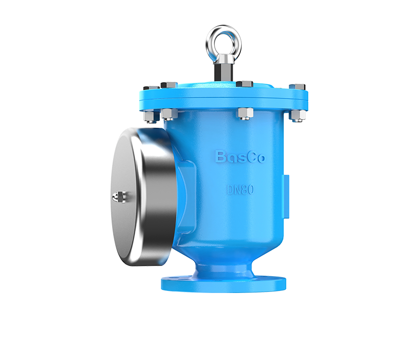

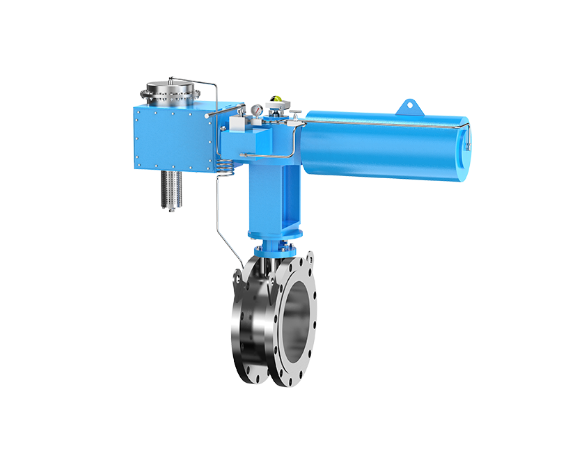










When I review a pressure vacuum relief valve, or PVRV, request, I do not begin with the tank nozzle size. I begin with the events that make gas enter or leave the tank. Liquid transfer, vapor-space heating and cooling, product volatility, blanketing, piping resistance, and the tank pressure limits all affect the final selection.
In practical terms, the sizing sequence is: collect the tank and process data, calculate normal inbreathing and outbreathing separately, check emergency venting independently, coordinate the set points with the tank limits, and then use tested manufacturer capacity curves to select and verify the valve. A nominal connection size alone does not prove capacity.
This guide explains that sequence from a BasCo engineer's perspective. It is intended to help tank designers, process engineers, and buyers prepare a reliable sizing basis and a complete request for quotation. Project calculations should always use the applicable edition of API 2000, local regulations, the tank design code, process hazard studies, and the actual rated data supplied for the proposed valve.

What Does API 2000 Require for PVRV Sizing?
API 2000 addresses venting requirements for atmospheric and low-pressure storage tanks. Its sizing approach helps the engineer identify how much gas or vapor must move through a vent during defined operating and emergency scenarios. The result is a required venting rate under stated conditions, not an automatic valve diameter.
Scope of API 2000
The method is commonly applied to aboveground storage tanks containing petroleum and petroleum products. The engineer must still confirm the current standard edition, tank construction code, service, pressure range, vapor behavior, and governing regulations. Refrigerated service, reactive products, unusual two-phase behavior, polymerizing fluids, or systems outside the standard's scope may need a separate study.
We also check whether a conservation vent is appropriate for the service. A PVRV can reduce routine vapor losses and protect the tank against excessive pressure or vacuum, but it is only one part of the tank protection system. Blanketing regulators, emergency vents, flame arresters, piping, and control safeguards can all influence the design.
Normal Venting vs. Emergency Venting
Normal venting covers routine inbreathing and outbreathing. Typical causes are liquid withdrawal, liquid filling, vapor-space cooling, vapor-space heating, and product vaporization. These loads are normally handled by a PVRV or another normal venting device.
Emergency venting covers abnormal heat input or other specified emergencies. External fire exposure is the classic case. An emergency relief vent may be required because the emergency load can be much greater than the normal breathing load. Do not combine the two concepts casually or assume a normal PVRV alone provides the required fire-case capacity.
What Information Do You Need Before Sizing a PVRV?
A calculation is only as reliable as its inputs. Incomplete RFQs often provide only the tank volume and nozzle size. That is not enough. At BasCo, we want to understand both the tank limits and the process events that create venting demand.
Tank Design Data
Record the tank type, total and working volume, diameter, shell height, roof type, design pressure, and design vacuum. Include the governing tank code and any corrosion allowance or special roof limitation relevant to pressure control. The tank's maximum allowable pressure and vacuum form the outer protection boundaries.
Liquid Transfer Rates
Provide the maximum credible filling and emptying rates, not only the usual operating rates. Liquid withdrawal creates vapor-space volume that must be replaced by incoming gas. Filling displaces gas and vapor that must leave the tank. Consider pump capacity, simultaneous transfer, valve line-up, gravity transfer, and credible control failures.
Product and Vapor Data
Identify the stored product, liquid density, vapor pressure, operating temperature, flash point where relevant, and any vapor-generation behavior. For a low-volatility liquid, displaced volume may dominate. For a volatile product or warm fill, evaporation can add a material outbreathing load. The process engineer should define the appropriate vapor properties and basis.
Site and Operating Conditions
Ambient temperature range, solar exposure, rainfall, altitude, wind, insulation, operating pressure, blanketing gas, and connected vapor systems can change the result. Also state whether the valve discharges directly to atmosphere or into a header. A valve connected to piping sees a different pressure-loss environment from a bare valve tested with open discharge.
| Input group | Minimum useful data | Why it matters |
|---|---|---|
| Tank | Type, volume, diameter, height, design pressure, design vacuum | Defines geometry and protection limits |
| Transfer | Maximum filling and withdrawal rates | Drives liquid-movement breathing loads |
| Product | Fluid, density, vapor pressure, temperature, volatility | Supports vapor-generation assessment |
| Operation | Normal pressure, blanketing pressure, credible scenarios | Coordinates valve settings and margins |
| Installation | Piping, headers, flame arresters, screens, weather hoods | Identifies installed-system pressure loss |
How Do You Calculate Normal Inbreathing Capacity?
Inbreathing is the flow entering the tank when the internal pressure tends to fall. We evaluate the credible withdrawal load and the thermal load on the vacuum side, using the procedures and units required by the applicable API 2000 edition.
Inbreathing Caused by Liquid Withdrawal
When a pump removes liquid, the vapor space expands. If replacement gas cannot enter fast enough, the internal pressure drops and the tank can deform or collapse. The maximum credible withdrawal rate is therefore a primary input. The calculation converts liquid movement into the required air or gas inflow on the selected reference basis.
Thermal Inbreathing
A falling ambient temperature, cold rain, or other cooling can contract vapor and cause condensation. This creates additional vacuum demand even when no pump is operating. Thermal breathing depends on the standard's method and applicable tank factors. Ignoring thermal inbreathing is a common reason a valve passes a transfer-only check but remains undersized for real service.
Total Required Vacuum Capacity
Combine concurrent vacuum-producing effects as required by the chosen calculation basis. State the final required vacuum flow, reference conditions, gas properties, and allowable tank vacuum at that flow. Keep this value separate from the pressure-side requirement. The two directions often have different demands and different performance curves.

How Do You Calculate Normal Outbreathing Capacity?
Outbreathing is the flow leaving the tank when internal pressure rises. The pressure-side calculation considers liquid filling, thermal expansion of the vapor space, and product vaporization where applicable.
Outbreathing Caused by Tank Filling
Incoming liquid displaces gas and vapor. The maximum credible fill rate establishes a core outbreathing load, but the relationship is not always a simple one-to-one conversion. Flashing, warm product, vapor generation, and the specified reference conditions can increase the required gas-volume capacity.
Thermal Outbreathing
Solar heating or a rise in ambient temperature expands the vapor space and may increase evaporation. API 2000 provides a structured basis for assessing thermal breathing. Tank size, insulation, paint or surface characteristics, and operating environment may matter under the applicable method.
Product Vaporization
High-volatility liquids require special attention. Filling may disturb the liquid, introduce heat, or create vapor beyond simple displacement. Where the standard's general factors do not adequately describe the process, use process data, heat and mass balance, or other qualified engineering analysis. Never hide an uncertain vaporization load inside an unsupported safety factor.
Do You Need to Calculate Emergency Venting Separately?
Yes. Normal breathing and emergency relief have different causes and can have very different flow magnitudes. The project must determine whether external fire or another emergency case is credible and then evaluate it under the relevant standard, tank code, and site rules.
Fire Exposure
External fire can transfer heat into the wetted portion of a tank and generate vapor rapidly. The emergency venting study may consider wetted area, insulation, drainage, fire protection, product properties, environmental factors, and credit permitted by the governing rules. This analysis should be documented separately from routine PVRV breathing.
PVRV vs. Emergency Relief Vent
A PVRV typically controls routine pressure and vacuum near the normal operating range. An emergency relief vent is designed to provide large relieving capacity during defined emergencies. Some systems may credit multiple devices, but the engineer must verify their combined capacity and pressure behavior. A normal vent is not automatically a substitute for an emergency vent.
How Should You Select the Pressure and Vacuum Set Points?
The set points must sit between the normal operating range and the tank design limits, with enough allowance for tolerances, blanketing behavior, pressure accumulation, and installed losses. A narrow operating window demands careful coordination.
Pressure Set Point
The pressure pallet should remain closed during intended operation, including normal blanketing fluctuations, yet open early enough to keep the tank within its permissible pressure. Review the blanketing regulator set point, normal operating pressure, PVRV pressure setting, emergency vent setting, and maximum allowable tank pressure as one coordinated system.
Vacuum Set Point
The vacuum pallet must protect the tank before its allowable vacuum is exceeded. Check normal process fluctuations, nitrogen or air makeup behavior, the valve setting, setting tolerance, and the vacuum reached while the required flow passes through the valve and inlet system.
Set Point Is Not the Same as Full-Flow Capacity
This distinction prevents many selection errors. The set point describes the condition at which the valve begins to open according to its defined test basis. The valve needs additional pressure or vacuum differential to lift further and pass more flow. A valve set at 20 mbar does not necessarily deliver its published full capacity at 20 mbar. Always identify the pressure or vacuum at which the curve capacity is stated and confirm that this condition remains acceptable for the tank.

How Do You Convert the Required Venting Capacity into a Valve Size?
This is the point where the API calculation meets the actual equipment. The calculation gives the required pressure-side and vacuum-side flows. The manufacturer supplies tested capacity data for valve models, sizes, settings, and flow conditions. Selection is made by matching both.
Use Manufacturer Flow-Capacity Data
Read the correct curve for the model, nominal size, pressure or vacuum setting, pallet configuration, gas basis, and accessories. Plot or locate the required flow at the maximum allowable pressure or vacuum condition. The curve must show that the proposed valve can pass at least the required flow without pushing the tank beyond its allowed boundary.
Check Both Pressure and Vacuum Capacity
A single PVRV contains two functions, but it does not have one universal capacity number. Compare the required outbreathing flow with the pressure curve, and the required inbreathing flow with the vacuum curve. If the selected size passes one side but fails the other, it is not acceptable.
Identify the Governing Case
The governing case is the side or scenario that requires the larger effective valve size. It may be pressure flow for a fast filling operation, vacuum flow for rapid pump-out, or a case made critical by tight allowable pressure or high system loss. Document the non-governing side too. That record makes the final review traceable.

How Do Piping and Flame Arresters Affect PVRV Sizing?
A catalog curve commonly describes a defined test arrangement. The installed system may add resistance before or after the valve. Capacity must therefore be checked for the complete breathing path, not for an isolated component only.
Inlet Pressure Loss
Long or undersized inlet piping, fittings, blocked drains, and poor nozzle arrangements consume part of the available pressure differential. Excessive inlet loss can delay effective relief or destabilize valve operation. Keep the valve close to the tank when practical and calculate the inlet path for the governing flow.
Outlet Pressure Loss
A discharge pipe or vapor header can create backpressure. Consider pipe length, fittings, common-header interactions, vapor recovery equipment, and the possibility of simultaneous relief from several tanks. Confirm that the proposed valve performance data applies to the expected outlet condition.
Flame Arrester Pressure Drop
A flame arrester, insect screen, weather hood, or other accessory can reduce available capacity. Pressure drop may increase with flow and with contamination. If a flame arrester is required, use its tested pressure-drop data and account for inspection and maintenance conditions.
Combined Venting-System Capacity
The correct check allocates the allowable tank pressure or vacuum across the valve and all connected components. The bare valve's catalog capacity is not automatically the installed system capacity. BasCo can review the proposed valve together with relevant accessories when the complete system information is provided.
What Does an API 2000 PVRV Sizing Example Look Like?
Tank Design Inputs
Assume a fixed-roof storage tank with a working volume of 5,000 m³, a maximum filling rate of 900 m³/h, and a maximum withdrawal rate of 1,100 m³/h. The tank has defined pressure and vacuum limits, a nitrogen blanket, and a PVRV that discharges directly to atmosphere. The engineer has confirmed the product data, normal temperature range, and thermal-breathing basis.
Required Inbreathing Calculation
Using the applicable API 2000 procedure and the project's reference conditions, assume the withdrawal contribution and thermal contribution produce a total required inbreathing capacity of 1,420 Nm³/h. The calculation sheet records how concurrent loads were combined and defines the maximum permissible vacuum at the required flow.
Required Outbreathing Calculation
Assume the filling, thermal, and applicable vaporization checks produce a total required outbreathing capacity of 1,680 Nm³/h. The pressure side is larger in this example, but that does not yet prove it governs. The permissible pressure and the shape of each capacity curve still matter.
Required Emergency Venting Check
The fire-case study is completed separately. It determines that a dedicated emergency relief vent is required. Its capacity is selected under the emergency basis, while the PVRV continues to serve the normal breathing cases. Any permitted contribution from other devices is documented rather than assumed.
Valve Capacity Curve Selection
The engineer requests curves for a candidate BasCo 5100 end-of-line PVRV in DN100. For this teaching example only, assume the applicable tested curve shows 1,950 Nm³/h on the pressure side at the permitted accumulated pressure and 1,700 Nm³/h on the vacuum side at the permitted accumulated vacuum.
| Verification | Required flow | Illustrative available capacity | Margin | Result |
|---|---|---|---|---|
| Pressure side | 1,680 Nm³/h | 1,950 Nm³/h | 16.1% | Pass, subject to final curve and system-loss review |
| Vacuum side | 1,420 Nm³/h | 1,700 Nm³/h | 19.7% | Pass, subject to final curve and system-loss review |
Final Size Verification
The candidate passes both directional checks in the illustrative comparison. We then verify the set points, tank limits, tolerances, gas basis, materials, connections, accessory losses, discharge arrangement, and documentation. If a flame arrester or long vent line reduces the available margin below the project's acceptance criterion, we select a larger valve or revise the system.
The complete selection statement is therefore: BasCo 5100 → DN100 candidate → illustrative pressure capacity 1,950 Nm³/h and vacuum capacity 1,700 Nm³/h → both exceed the calculated demands → final acceptance pending project-specific certified curve and installed pressure-loss verification.

What Are the Most Common API 2000 PVRV Sizing Mistakes?
| Incorrect method | Possible consequence | Correct verification |
|---|---|---|
| Selecting by tank nozzle size | Valve capacity may be too low despite matching the flange | Compare required flows with tested pressure and vacuum curves |
| Ignoring thermal breathing | Vacuum or pressure demand is understated | Calculate transfer and thermal cases under the applicable method |
| Checking only pressure flow | Vacuum pallet may not protect the tank during pump-out or cooling | Verify both sides independently |
| Treating set pressure as full-flow pressure | Tank pressure at required capacity can exceed the limit | Read the full capacity curve at the permitted condition |
| Ignoring accessories and piping | Installed capacity is lower than bare-valve capacity | Calculate total system pressure loss |
| Combining normal and emergency concepts | Fire-case protection may be inadequate | Document normal and emergency relief checks separately |
What Information Should You Include in a PVRV RFQ?
A complete RFQ lets us check the engineering basis instead of guessing. Include calculations if they are available. If they are not, provide the raw tank and process data so the required scope can be discussed.
- Tank data: type, code, volume, diameter, height, roof, design pressure, and design vacuum.
- Process data: stored product, density, vapor properties, operating temperature, maximum filling rate, and maximum emptying rate.
- Operating conditions: normal pressure, blanketing medium and set point, ambient range, altitude, and credible scenarios.
- Required settings: pressure set point, vacuum set point, allowable accumulation, and required flow in each direction.
- Mechanical details: connection size and rating, body material, pallet and seat materials, corrosion requirements, and orientation.
- System details: inlet and outlet piping, vapor header, weather hood, insect screen, flame arrester, and emergency vent arrangement.
- Quality requirements: inspection plan, setting test, leakage test, flow or capacity documentation, material certificates, and project standards.
How Can You Verify That the Selected PVRV Is Correct?
Use a short, traceable review before approving the valve. The following sequence aligns the process calculation, tank limits, and actual equipment data.
- Confirm the applicable API 2000 edition, tank code, service scope, units, and reference conditions.
- Verify the maximum credible filling and withdrawal rates and the normal thermal-breathing basis.
- Record required outbreathing and inbreathing flows separately.
- Complete the emergency venting check as a separate documented analysis.
- Coordinate operating pressure, blanketing, PVRV settings, emergency settings, and tank design limits.
- Use the exact manufacturer curves for the proposed model, size, settings, and configuration.
- Check pressure and vacuum capacity at their permitted full-flow conditions.
- Include inlet loss, outlet backpressure, flame arrester drop, and other accessory losses.
- Document the governing case, available capacity, margin, materials, tests, and final approval basis.
If any input changes, repeat the affected checks. A higher pump rate, tighter set point, added flame arrester, new vapor header, or different product can change the governing case and the required size.
How Does BasCo Verify PVRV Performance?
Capacity selection depends on credible performance data. BasCo uses pressure and flow-capacity testing to evaluate breather valve behavior under defined test conditions. The test basis, valve configuration, setting, flow direction, and units must match the selection documents used for the project.
Which BasCo Pressure Vacuum Relief Valve Fits the Installation?
After the required capacities and settings are established, select the valve arrangement that fits the venting system. An end-of-line valve is commonly installed at an atmospheric termination. An in-line valve is designed for connection within a vapor piping system. The installation arrangement must be reflected in the pressure-loss and backpressure review.
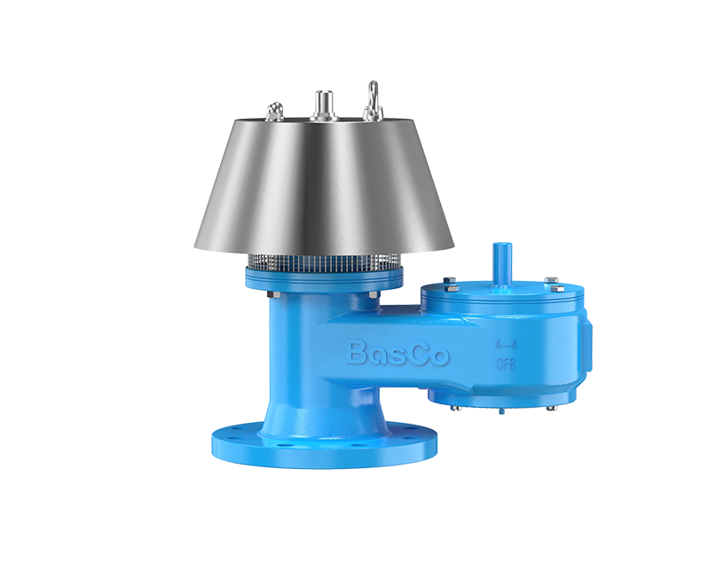
5100 End-of-Line PVRV
Explore the BasCo end-of-line pressure vacuum relief valve for tank breathing applications that terminate at the valve outlet.
View 5100 PVRV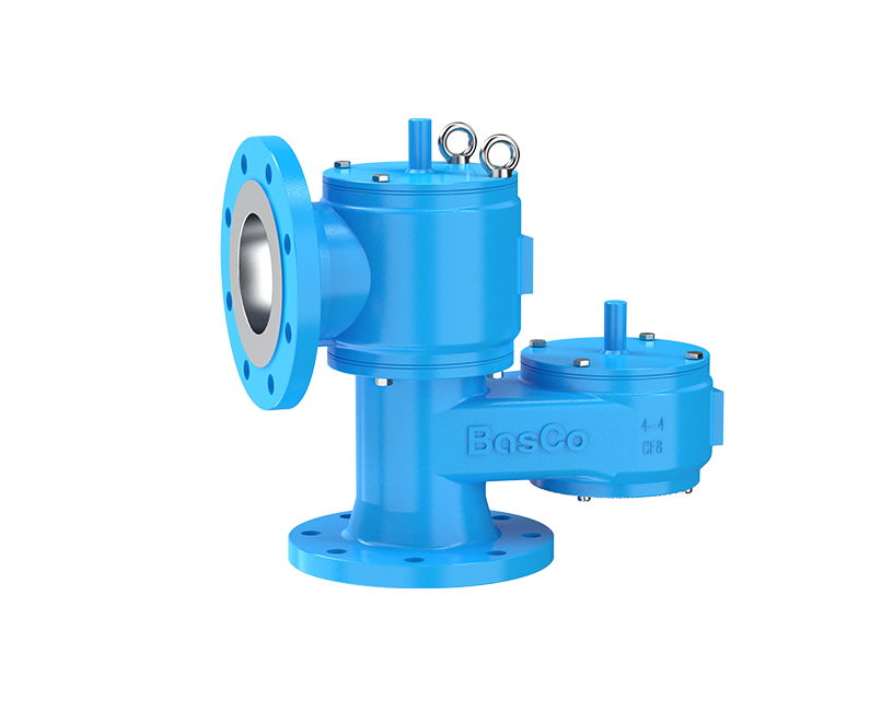
5200 In-Line PVRV
Explore the BasCo in-line pressure vacuum relief valve for systems connected to downstream vent or vapor piping.
View 5200 PVRVNeed a PVRV Sizing Check?
Send BasCo your tank data, transfer rates, pressure and vacuum limits, set points, product information, and installation details. Our team can review the selection basis and match the required capacity to an appropriate tested valve configuration.
Send Your Tank Data Explore BasCo PVRVsDisclaimer: This article provides general engineering guidance. It does not replace a project-specific calculation, the applicable edition of API 2000, governing codes and regulations, process safety review, or certified manufacturer performance data.