


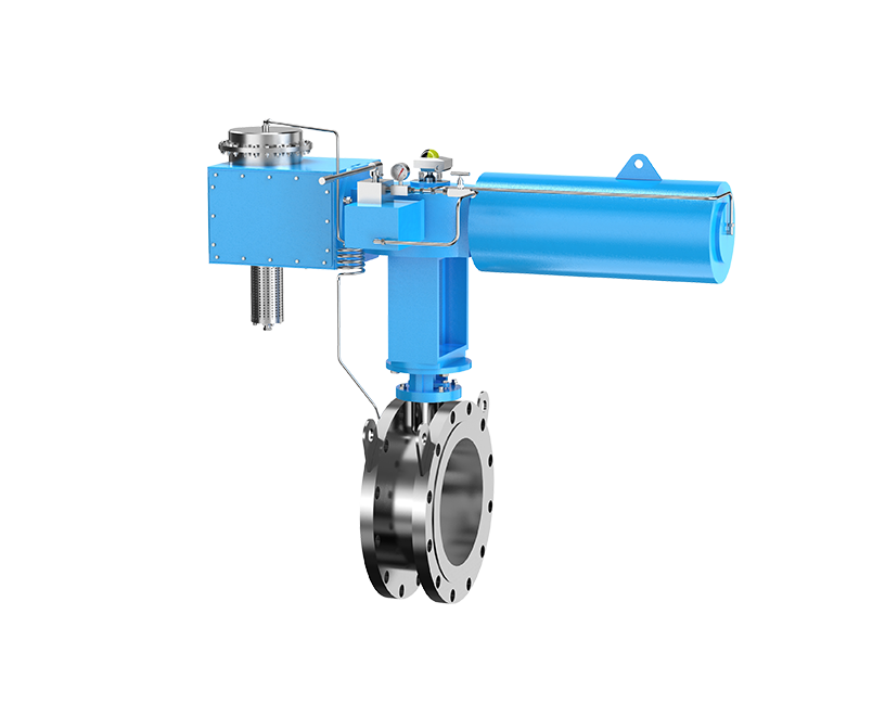










In storage tank design, a pressure vacuum relief valve (PVRV) is easy to underestimate. Engineers may focus first on the tank shell, process controls, and transfer equipment, while the pressure changes created by everyday operation receive less attention. Yet even small pressure or vacuum deviations can deform a low-pressure tank, increase vapor losses, damage seals, or shorten equipment life.
A PVRV, also called a breather valve or conservation vent, protects an atmospheric or low-pressure storage tank during normal breathing. It opens on the pressure side when vapor must leave the tank and opens on the vacuum side when air or inert gas must enter. Correct protection depends on the tank's allowable pressure and vacuum, the required inbreathing and outbreathing capacity, the stored medium, and applicable venting calculations such as API 2000.
This guide explains how a PVRV works, why storage tanks need one, how it differs from emergency relief and flame-protection devices, and what engineers and procurement teams should define before selecting a valve.
What Is a Pressure Vacuum Relief Valve (PVRV)?
A pressure vacuum relief valve is a self-actuated venting device designed to keep a storage tank within its allowable positive-pressure and vacuum limits. Under normal conditions, the valve remains closed to retain vapor. When tank pressure reaches the specified opening condition, the pressure pallet or mechanism lifts and releases vapor. When the tank develops sufficient vacuum, the vacuum side opens and admits air or another permitted gas.
PVRVs are commonly installed on fixed-roof atmospheric and low-pressure tanks. Unlike an open vent, a properly selected PVRV limits unnecessary vapor release because it opens only when the internal condition requires breathing. This supports tank integrity, product conservation, emission control, and safer operation.
A PVRV should not be treated as the only protection layer. Normal venting, emergency venting, flame propagation control, and process shutdown are separate functions that must be assessed as part of the complete tank protection system.
How Does a PVRV Work?
Pressure relief during outbreathing
Tank pressure rises when liquid enters the tank, vapor is generated, or the vapor space warms and expands. Once the pressure acting on the valve reaches the specified opening condition, the pressure element lifts and allows vapor to flow out. As pressure falls, the valve reseats to reduce continued vapor loss.
Vacuum relief during inbreathing
Vacuum can develop when liquid is withdrawn, vapor condenses, or the vapor space cools. When the negative pressure reaches the vacuum setting, the vacuum element opens and allows air or an approved blanketing gas to enter. This reduces the risk of shell or roof deformation caused by insufficient inbreathing capacity.
Resealing and operating margin
The valve does not remain open continuously. It stays closed during most normal operation and cycles as pressure or vacuum reaches its operating threshold. Set pressure, relieving pressure, blowdown, leakage performance, and tank design limits must therefore be considered together. A valve connection size alone does not prove that the installed device has adequate capacity.
Pressure Vacuum Relief Valve Principle Animation — showing how a PVRV responds to positive tank pressure and vacuum conditions.
How Is Normal PVRV Venting Different from Emergency Relief?
A PVRV primarily handles routine inbreathing and outbreathing caused by liquid movement and temperature change. An emergency relief valve or emergency vent addresses abnormal scenarios that may create much greater vapor generation, such as external fire exposure or certain process upsets. The required protection depends on the tank design, stored product, applicable code, and documented relief basis.
| Device | Primary Function | Typical Role | Important Limitation |
|---|---|---|---|
| PVRV | Controls normal tank pressure and vacuum | Reclosing normal vent | Must be sized for required inbreathing and outbreathing |
| Emergency relief valve or vent | Provides additional capacity during defined abnormal scenarios | Emergency protection layer | Does not replace normal venting analysis |
| Rupture disk | Opens by bursting at a specified condition | Non-reclosing pressure relief | Requires replacement after activation |
| Flame arrester | Stops flame propagation for its approved service conditions | Passive flame protection | Does not regulate tank pressure or replace a vent |
Why Do Storage Tanks Need PVRVs?
Thermal inbreathing and outbreathing
The gas and vapor in a tank expand as temperature rises and contract as temperature falls. Solar heating and daytime temperature increases can create outbreathing demand. Cooling, rain, or nighttime temperature reduction can create inbreathing demand. The required capacity depends on the tank and the conditions defined by the selected design method.
Liquid filling and withdrawal
Filling reduces vapor-space volume and pushes vapor toward the vent. Withdrawal increases vapor-space volume and requires replacement gas to enter. Transfer rates can create a larger venting demand than temperature change, so maximum pump-in and pump-out rates must be included in the calculation.
Product conservation and fugitive-emission control
An open vent allows vapor to escape whenever internal pressure changes. A correctly set and maintained PVRV retains vapor until venting is necessary. This can reduce routine product loss, odor, and emissions, although actual environmental compliance depends on the complete vapor-control system and local requirements.
What Types of PVRVs Are Available?
End-of-line PVRVs
An end-of-line PVRV discharges directly to the atmosphere and is normally installed at the termination of a tank vent. Weather protection, discharge direction, condensate management, environmental exposure, and safe vent location should be considered during installation.
In-line PVRVs
An in-line PVRV connects to vent piping or a vapor-handling system. Because downstream piping, fittings, headers, and other devices create resistance, the installed backpressure and total system pressure drop must be checked against valve performance and tank limits.
Pilot-operated PVRVs
A pilot-operated PVRV uses a pilot system to control the main valve. It may be selected when tight sealing, stable control, high capacity, or operation close to the desired pressure limit is important. Suitability still depends on the medium, operating environment, maintenance capability, and verified flow data.
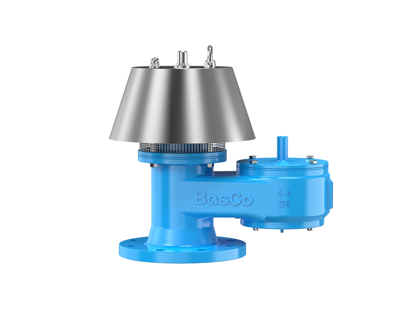
5100 End-of-Line Pressure Vacuum Relief Valve
Designed for end-of-line tank venting where pressure and vacuum protection discharge directly to the atmosphere.
View product details →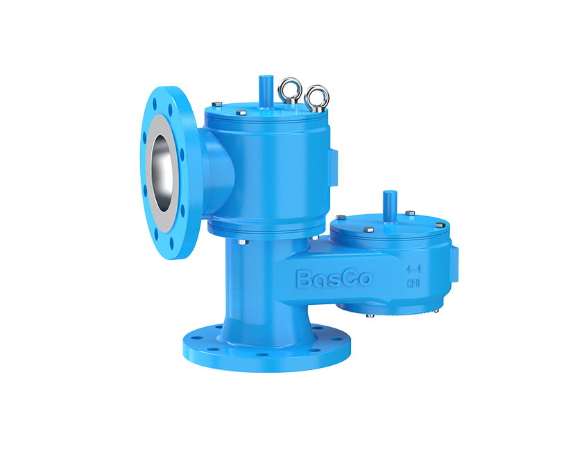
5200 In-Line Pressure Vacuum Relief Valve
Suitable for installation within vent piping or a connected vapor-handling system, subject to system pressure-drop evaluation.
View product details →
5500 Pilot-operated Pressure Vacuum Relief Valve
A pilot-controlled configuration for projects requiring carefully controlled opening behavior and low vapor leakage.
View product details →Compare BASCO Pressure Vacuum Relief Valves
Review end-of-line, in-line, pilot-operated, and flame-arrester-integrated configurations for storage tank vent systems.
View the PVRV Product RangeHow Do PVRVs Work with Flame Arresters?
A PVRV controls pressure and vacuum; a flame arrester limits flame propagation. When flammable vapor service requires both functions, the two devices must be evaluated as an integrated venting assembly. Adding a flame arrester can increase flow resistance, and contamination of the arrester element can increase that resistance further.
An end-of-line arrangement is used where the vent terminates at atmosphere and the defined flame hazard occurs at that termination. An in-line arrangement is used within piping, but the correct flame-arrester type and location depend on the possible combustion event, gas group, operating temperature, piping geometry, run-up distance, and the device's tested approval conditions.
Integrated products can simplify layout and interface management. They do not eliminate the need to verify certified service limits, combined capacity, pressure drop, inspection access, drainage, and maintenance intervals.
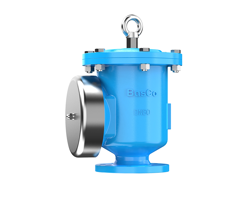
5600 End-of-line PVRV with Integrated Flame Arrester
Combines tank pressure-vacuum control with an end-of-line flame-protection function in one coordinated assembly.
View product details →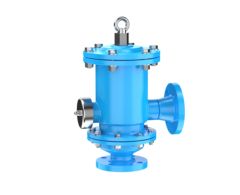
5800 In-line PVRV with Integrated Flame Arrester
Combines pressure-vacuum control and flame protection for an in-line vent-piping configuration.
View product details →How Do You Size a PVRV According to API 2000?
Sizing starts with the tank's documented design limits, not with the nozzle size. The required normal venting capacity should be calculated for the applicable inbreathing and outbreathing cases. API 2000 is widely used for atmospheric and low-pressure storage tank venting, but the project must confirm the applicable edition, local regulations, owner specifications, and any additional design standard.
| Venting Case | Typical Cause | Data Needed | Engineering Check |
|---|---|---|---|
| Normal outbreathing | Liquid filling and thermal expansion | Maximum filling rate, tank characteristics, product properties, temperature basis | Valve capacity at the permitted relieving pressure |
| Normal inbreathing | Liquid withdrawal and thermal contraction | Maximum withdrawal rate, tank characteristics, temperature basis | Valve capacity before the tank vacuum limit is exceeded |
| Emergency venting | External fire or another defined abnormal event | Wetted area, insulation or drainage credit where permitted, process scenario | Separate emergency capacity and relief path |
Use the manufacturer's certified or verified capacity data at the specified flowing pressure or vacuum. Capacity at an arbitrary pressure cannot be substituted without confirming that the tank's allowable accumulation is respected. Piping losses, flame arresters, vent headers, screens, and backpressure may reduce the capacity available to the tank.
How Do You Select the Right PVRV?
Selection checklist
- Tank limits: maximum allowable positive pressure and vacuum, including any operating margin required by the project.
- Set points: pressure and vacuum settings coordinated with normal operating pressure, blanketing control, emergency relief, and tank design limits.
- Capacity: required inbreathing and outbreathing flow under the selected standard and actual operating cases.
- Installation: end-of-line or in-line configuration, nozzle size, flange standard, orientation, piping losses, backpressure, and discharge location.
- Process medium: vapor composition, corrosiveness, toxicity, polymerization or fouling tendency, and compatibility with body, trim, seat, diaphragm, and gasket materials.
- Operating environment: minimum and maximum temperature, rain, dust, icing, condensation, salt exposure, and maintenance access.
- Performance and documentation: leakage requirement, capacity basis, inspection and test certificates, materials, applicable approvals, and project documentation.
The set pressure should be high enough to avoid unnecessary cycling during routine operation but low enough to protect the tank with the required margin. Where inert-gas blanketing is used, the blanketing regulator and PVRV settings must be coordinated so that the devices do not conflict or cause excessive gas consumption.
What Are the Most Common PVRV Selection Mistakes?
- Selecting by flange size alone: identical connection sizes can have different flow capacities and pressure-drop characteristics.
- Confusing set pressure with relieving pressure: the tank must remain within its allowable limit at the flow condition used to rate capacity.
- Ignoring the vacuum case: pump-out and rapid cooling can damage a tank even when pressure relief is adequate.
- Omitting downstream resistance: in-line piping, flame arresters, headers, and fouling can affect available capacity.
- Using incomplete process data: uncertain transfer rates, vapor properties, or temperature limits can lead to incorrect materials or sizing.
- Combining functions without system review: a PVRV, flame arrester, blanketing regulator, vapor recovery system, and emergency vent must operate as a coordinated system.
How Should a PVRV Be Installed and Maintained?
Install the valve in the orientation specified by the manufacturer, normally upright, on a connection that is adequately supported and free of construction debris. Vent piping should avoid liquid pockets and unnecessary restrictions. Discharge must be routed to a safe location, and the design should account for rain, condensate, icing, insect entry, and other environmental effects without adding unverified restrictions.
Inspection frequency should reflect service severity and site experience. Typical checks include pallet or mechanism movement, seat condition, gasket and diaphragm condition, corrosion, deposits, weather hood condition, drains, fasteners, and any flame-arrester element. After maintenance, confirm correct assembly, settings, tightness, and functional performance according to the manufacturer's instructions and site procedures.
What Information Is Required for a PVRV Quote?
| Required Information | Why It Matters |
|---|---|
| Tank type, dimensions, design pressure, and design vacuum | Defines the protected equipment and allowable operating envelope |
| Maximum filling and withdrawal rates | Supports working outbreathing and inbreathing calculations |
| Required pressure and vacuum settings | Determines opening behavior and coordination with other devices |
| Calculated capacity and calculation basis | Allows valve performance to be matched to the design case |
| Stored liquid and vapor composition | Guides material compatibility, sealing, and emissions considerations |
| Operating and design temperatures | Affects materials, sealing components, and environmental suitability |
| Connection size, flange standard, and installation arrangement | Confirms physical interface and whether end-of-line or in-line design is needed |
| Backpressure, connected piping, and flame arrester details | Identifies restrictions that can affect installed performance |
| Required codes, approvals, tests, and documentation | Aligns the proposal with regulatory, owner, and procurement requirements |
Need Help Selecting a PVRV?
Send BASCO your tank limits, venting calculations, operating conditions, medium, connection requirements, and required documentation. The engineering team can review the application and recommend a suitable configuration.
Contact BASCOConclusion
A PVRV is a primary protection device for the normal breathing of atmospheric and low-pressure storage tanks. It helps control pressure during filling and heating, admits air or permitted gas during withdrawal and cooling, and reduces unnecessary vapor loss while closed.
Reliable protection depends on more than selecting a nominal valve size. Engineers should define tank limits, calculate all applicable venting cases, coordinate pressure and vacuum settings, review installed pressure losses, select compatible materials, and maintain the complete vent system. Emergency relief and flame protection should be evaluated as separate but coordinated layers.
FAQ
What is a pressure vacuum relief valve used for?
It protects an atmospheric or low-pressure storage tank against excessive positive pressure and vacuum during normal filling, withdrawal, heating, and cooling.
Is a PVRV the same as an emergency vent?
No. A PVRV normally handles routine tank breathing. An emergency vent provides additional relief capacity for defined abnormal conditions. A project may require both.
What happens if a tank has no adequate vacuum relief?
If gas cannot enter fast enough during liquid withdrawal or cooling, the resulting vacuum can deform the roof or shell and may cause tank collapse.
What is API 2000?
API 2000 is a widely used standard for venting atmospheric and low-pressure storage tanks. The project should confirm the applicable edition and any local or owner-specific requirements.
Can a flame arrester replace a PVRV?
No. A flame arrester limits flame propagation under its approved service conditions, while a PVRV controls tank pressure and vacuum. When both are required, their combined flow resistance and certified limits must be evaluated.