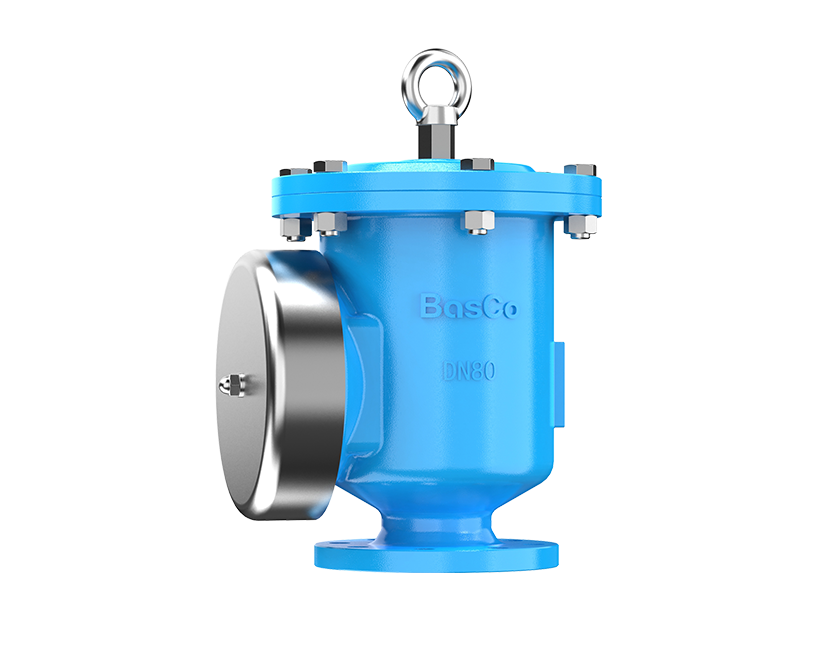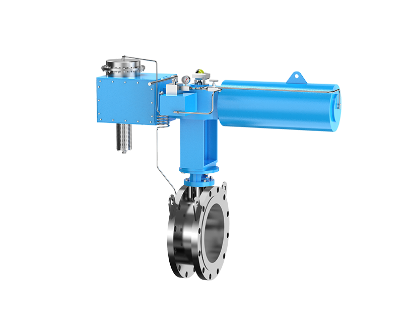


In my experience working with hazardous gas and vapor systems, flame arresters are often treated as simple accessories—installed late in the design, placed where space allows, and assumed to “just work”. In reality, flame arrester installation distance is one of the most misunderstood and underestimated variables in explosion protection. I've seen well-specified flame arresters fail not because of poor manufacturing quality, but because they were installed in the wrong location for the actual flame development regime in the pipeline.
With the release of ISO/IEC 80079-49:2024, the industry finally has clearer expectations around how flame arresters should be selected, positioned, and evaluated in real operating conditions—not just idealized test setups. In this article, I want to walk through the engineering logic behind installation distance, connect it directly to flame acceleration behavior, and explain where compliance risks usually hide.
When we talk about installation distance, we're not talking about a random number pulled from a table. Distance directly determines which combustion regime the flame arrester will actually encounter when ignition occurs. In long pipelines, flame propagation is not static—it evolves rapidly as pressure waves, turbulence, and confinement effects interact.
In practical terms, this means a flame arrester installed too far from a potential ignition source may be exposed to a flame speed and pressure profile it was never designed to handle. Conversely, installing a high-grade detonation flame arrester unnecessarily close to the ignition source can introduce excessive pressure drop, maintenance burden, and cost without adding real safety value.
ISO/IEC 80079-49:2024 emphasizes this dynamic behavior by requiring engineers to consider real pipeline geometry, gas group, and expected flame acceleration, rather than relying on simplified distance assumptions.
One of the most common misconceptions I encounter is the idea that a flame is either a deflagration or a detonation, as if these are fixed states. In reality, flame propagation inside a confined pipe typically progresses through three distinct stages as distance increases.
Initially, ignition produces a deflagration, where the flame front moves at subsonic speed. As the flame travels down the pipe, turbulence increases, pressure waves reflect from pipe walls, and the flame accelerates. This leads to a non-stable detonation phase, where flame speed and pressure fluctuate violently. If sufficient distance and confinement exist, the flame can finally transition into a stable detonation, with supersonic flame speed and a coupled shock wave.
From a protection standpoint, the non-stable detonation phase is often the most destructive. Pressure peaks can exceed those of stable detonation, and flame arresters not designed for this regime may fail instantly.
This is why ISO/IEC 80079-49:2024 explicitly discourages distance-only thinking and pushes engineers to evaluate which combustion phase is realistically expected at the arrester location.

Selecting the right flame arrester starts with understanding what it is designed to stop. In practice, I classify flame arresters based on the most severe combustion regime they are certified to withstand, not on marketing labels.
Deflagration flame arresters are only suitable where flame acceleration remains limited. Stable detonation flame arresters can handle higher loads, but they may still fail if exposed to non-stable detonation conditions. Only flame arresters certified for non-stable detonation can reliably protect systems where long pipelines, obstacles, or high-reactivity gases are present.
This distinction is critical, because installing a stable detonation arrester in a zone where non-stable detonation can develop is one of the most common—and dangerous—selection mistakes I see in audits.
Gas properties fundamentally change flame behavior. ISO standards classify gases by Maximum Experimental Safe Gap (MESG), which reflects how easily a flame can pass through narrow openings. Lower MESG values correspond to higher explosion severity.
Hydrogen, for example, belongs to the highest risk group, with extremely rapid flame acceleration and low ignition energy. In such cases, distances that might be acceptable for hydrocarbon vapors become completely unsafe.
From an engineering perspective, higher gas groups mean:
This is why ISO/IEC 80079-49:2024 aligns gas group classification with installation logic, rather than treating them as independent variables.
L/D—the ratio of pipeline length to diameter—is often quoted as a simple indicator of flame acceleration potential. While it's useful, I caution against treating L/D as a universal rule.
In straight, smooth pipes under laboratory conditions, L/D thresholds can roughly indicate when deflagration transitions to detonation. However, real pipelines are rarely ideal. Valves, elbows, diameter changes, and surface roughness all accelerate flame development. In many real systems, dangerous regimes occur at much lower L/D values than tables suggest.
ISO/IEC 80079-49:2024 reinforces this by requiring engineers to consider pipeline complexity, not just nominal length.
Typical engineering interpretation framework:
|
Gas Group |
L/D Range |
Expected Flame Regime |
Minimum Arrester Capability |
|
IIA–IIB3 |
<50 |
Deflagration |
Deflagration arrester |
|
IIA–IIB3 |
50–120 |
Non-stable detonation |
Non-stable detonation arrester |
|
IIB–IIC |
<30 |
Deflagration |
Deflagration arrester |
|
IIB–IIC |
30–120 |
Non-stable detonation |
Non-stable detonation arrester |
This table should never replace engineering judgment—it should trigger it.

This question comes up frequently, especially in retrofit projects where space is limited. The short answer is: yes, but only with proper justification.
If engineers can demonstrate—through testing, validated modeling, or conservative arrester selection—that the flame arrester will not be exposed to a more severe regime than it is certified for, longer distances may be acceptable. This often involves upgrading to a higher-grade detonation arrester rather than relocating equipment.
However, ISO/IEC 80079-49:2024 makes it clear that assumptions must be documented and defensible. Simply stating that “similar systems have worked before” is no longer sufficient from a compliance standpoint.
Installing flame arresters in series is sometimes proposed as a workaround for excessive distance. In my experience, this approach is frequently misunderstood.
Two deflagration flame arresters installed in series do not automatically equal a detonation flame arrester. Flame acceleration between arresters can still occur, especially if spacing and pipe geometry promote turbulence.
Series installation only makes sense when:

Structural diagram of BASCO Flame Arrester
This is where real installations diverge most sharply from standards tables. Every disturbance in a pipeline—elbows, reducers, valves, or rough internal surfaces—acts as a flame accelerator.
From an engineering standpoint:
As a result, a system with multiple elbows may reach non-stable detonation conditions in half the distance predicted for a straight pipe. ISO/IEC 80079-49:2024 explicitly requires these factors to be considered in installation assessment.
Orientation is often overlooked, yet it has direct implications for reliability. Horizontal and vertical installations experience different contamination, drainage, and thermal behaviors.
Vertical installations may accumulate condensate or solids on the flame element, increasing blockage risk. Horizontal installations near vibration sources can suffer from mechanical fatigue if not properly supported.
ISO/IEC 80079-49:2024 places increased emphasis on installation integrity over time, not just initial compliance. In my view, orientation should always be reviewed alongside maintenance strategy.
The most dangerous mistakes I see are not due to ignorance, but oversimplification. Engineers often reduce complex standards to single numbers or generic rules.
ISO/IEC 80079-49:2024 was developed precisely to close these gaps by forcing a more holistic evaluation.
Installation distance compliance does not end at commissioning. Flame arresters are dynamic safety devices whose effectiveness degrades without proper oversight.
From my perspective, effective lifecycle management includes:
This aligns directly with ISO/IEC 80079-49:2024's lifecycle philosophy, which treats flame arresters as active safety components rather than passive fittings.
Flame arrester installation distance is not about memorizing limits—it's about understanding flame behavior, gas properties, and real pipeline conditions. ISO/IEC 80079-49:2024 raises the bar by demanding that engineers justify their decisions with logic, not habit.
In my work, the most reliable systems are designed by teams who treat flame arresters as part of an integrated explosion protection strategy, not as standalone devices. If you're reviewing an existing installation or designing a new one, I strongly recommend stepping back from tables and asking a more fundamental question: What flame regime will my system actually produce at this location?
If you'd like to discuss specific pipeline configurations, gas groups, or compliance challenges under ISO/IEC 80079-49:2024, I'm always happy to share practical insights from real projects.

How to Size a Pressure Vacuum Relief Valve According to API 2000
2026-08-18Flame Arrester Guide: Types, Applications, Selection, and Industrial Solutions
2026-08-04Common Causes of Dust Collector Explosions and How to Protect Against Them
2026-07-13BasCo conducts "CPR+AED Emergency Training to Strengthen Workplace Life Safety Defense"
2026-06-18Copyright © Jiangsu Bafang Safety Device Co., LTD. All Rights Reserved