Liquefied natural gas (LNG) storage looks calm from the outside, but every tank is a living system with heat ingress, inventory stratification, dynamic fill cycles, and boil-off gas (BOG) management constantly pushing and pulling on pressure.
Selecting the right pressure safety devices for an LNG tank terminal is not just a sizing exercise—it's a system decision that has to harmonize mechanical design limits, process control responses, flare capacity, and maintainability. This guide walks through a practical, code-aligned approach for engineers and terminal operators who want protection that is both robust and operationally efficient.
The goal is straightforward: prevent overpressure and underpressure while minimizing product loss and spurious lifts. In practice, that means relief devices that open early enough to stay below mechanical limits but late enough to avoid routine venting; at least two full-duty paths so capacity is always available during maintenance; vacuum protection that accounts for pump-out, cooldown, and condensation transients; and materials and geometries that work at cryogenic temperatures without freezing, binding, or leaking. The devices themselves are only half the story. Equally important is the integration with BOG compressors, ESD systems, and the flare or vent stack so that normal controls handle upsets and safety devices are a last, reliable line of defense.
Industry Insight: The worst credible vapor generation scenarios at LNG tanks are rarely single-point events. A power failure that trips BOG compressors while rapid filling continues can quickly compound heat ingress and rollover risks. Design your relief envelope around multi-cause scenarios, not one-offs.
Most terminals rely on NFPA 59A for LNG facility requirements and API 521/API 2000 for pressure-relief and depressuring guidance. European projects often map to relevant EN and ISO standards, while ASME BPVC establishes vessel MAWP rules and testing conditions. From a selection standpoint, these references guide allowable accumulation, set pressure philosophy, sizing methods for vapor and two-phase relief, and documentation requirements. Functional safety for ESD shutdown architectures is typically governed by IEC 61508/61511, defining how safety integrity (SIL) is justified and verified. The practical takeaway: align PSV setpoints at or below tank MAWP with code-permitted accumulation, prove that first-opening valves lift before control limits, and document how controls, interlocks, and relief combine to keep operation inside the safe envelope.

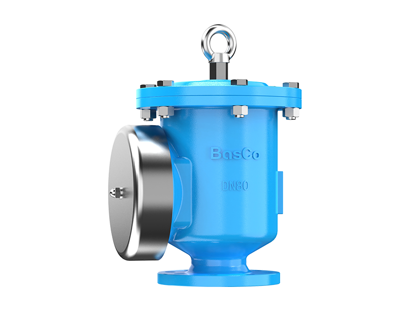
PRVs prevent overpressure by giving vapors a controlled escape path once operating pressure approaches the setpoint. In LNG service, balanced-bellows and pilot-operated valves are favored because they handle variable backpressure from flare headers, deliver tight blowdown, and minimize leakage in low-temperature gas service. Seating integrity matters: metal seats often maintain tightness better under cryogenic shrinkage and icing conditions than soft seats, provided the materials are methane-compatible and impact-tough at temperature.
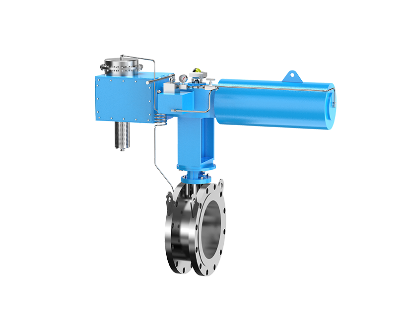
ESD valves provide rapid isolation across tanks, transfer lines, compressors, and ship/road loading arms. They are sized for fast closure, fail-safe actuation, and tight shutoff—even at cryogenic temperatures. Modern SIL-rated ESD systems integrate partial-stroke testing and diagnostics so operators can validate readiness without taking the plant offline. The ESD system should act first whenever controls indicate an upset is correctable by isolation; PRVs should only lift when the event has outpaced normal and protective controls.
Every blocked-in, LNG-wetted or subcooled line deserves a small thermal relief valve to handle thermal expansion from warm-up or solar heat gain. Dedicated vacuum relief protection is equally critical. Pump-out, cooldown, and sudden condensation can create external pressure that threatens tank integrity; vacuum relief devices must be sized and located to prevent collapse while staying clean and ice-free.
Set PSVs at or below the tank MAWP, with allowable accumulation per the governing code. Ensure the first device opens below the mechanical limit and before any control limit that could otherwise trip equipment into unstable states. Terminals often split required capacity across two or three PRVs per tank. The first-to-open PSV carries enough capacity to hold the tank below the accumulation limit for common upsets; the second-to-open (staggered setpoint or pilot trim) provides additional margin for less likely, higher-load events. This arrangement reduces nuisance lifts while guaranteeing capacity if an event escalates.
Two full-capacity relief paths per tank is a practical minimum. Isolation valves are permissible when they enable maintenance, but they must be managed—key-interlocks or car-seal programs ensure that at least one full-capacity path is always in service. Good layouts feature roof access platforms, removable spools, lifting points, and test connections that support in-situ valve proving. Design in instrument taps and monitored tell-tales so operators can verify seat integrity without breaking containment.
Design teams sometimes underweight vacuum scenarios because LNG tanks are“vapor positive” most of the time. In practice, quick pump-out, cooldowns, and rapid condensation during weather shifts can pull the tank into external pressure territory. Dedicated vacuum valves sized for credible transients prevent shell buckling. Locate inlets to avoid icing, and if necessary, use extended bonnets, insulation, and heat tracing to ensure operability when temperatures plummet.
All wetted and trim materials must be methane-compatible and retain toughness at cryogenic temperatures. Stainless steels commonly used in cryogenic service behave differently at -162°C; verify impact test data and weld procedures accordingly. Extended bonnets and proper insulation reduce heat leak into the valve body and help keep the spring and actuation components out of the cold zone. Where icing risk persists—especially on vent discharges—select trim and geometries that shed ice, consider heated tips at the flare or vent stack, and ensure drains and tell-tales remain operable.

Keep the inlet pressure drop to 3% of set pressure or less to avoid capacity shortfall and chatter. Short, large-bore piping with smooth radii pays dividends when the PSV needs every kilogram per second it can pass. On the outlet, control both superimposed and built-up backpressure within the valve's rated limits. For pilot-operated valves, confirm how the pilot senses pressure and how backpressure affects blowdown; where backpressure is variable, balanced-bellows or backpressure-compensated pilots are usually the safest bet. If headers are long or shared, model dynamic relief to confirm you won't see interacting surges that push a PSV outside its certified performance envelope.
A rupture disk upstream of a PSV is a proven way to protect the seat from icing and eliminate fugitive emissions through minute leakage. The disk must be sized and certified for flow in combination with the PSV, and the space between disk and valve must be monitored using a tell-tale line or pressure switch. Any pressure rise here signals a compromised disk or a leaking seat; integrate that alarm into your maintenance program so you can intervene before a lift or release.
LNG terminals typically route relief to a cold flare or high-elevation vent stack. Design the system with knock-out capacity for any condensables and tip heating or steam assistance to prevent ice build-up and flame instability. Limit exit velocities to avoid flame lift-off and ensure pilots or ignition systems are reliable in wind and icing conditions. Verify that radiant heat and dispersion criteria are met for both flaring and any credible cold venting events, and confirm stack height and location keep site exposures inside your risk acceptance thresholds.
Most LNG tank relief is vapor, but rollover, sloshing during rapid filling, or agitation from mixing can entrain liquid and create two-phase flow at the relief pickup. Because two-phase modeling adds uncertainty and often increases required area, reduce the risk by locating pickups in the vapor space, using dip-legs or demisters, and orienting internals to resist slosh ingress. When a two-phase scenario remains credible, choose sizing methods that are conservative and documented, and validate that downstream flare hydraulics tolerate the higher density mixture without over-pressuring the header.
Expert Perspective: Rollover relief is often underestimated. Monitoring density and temperature profiles across the tank stratification layers is your cheapest insurance. When a layer inversion is predicted, pre-mixing or controlled withdrawal can reduce the boil-off surge that would otherwise push relief demand near flare limits.
Relief setpoints and capacities must be coordinated with BOG compressor control logic, ESD trip levels, and flare capacity. The objective is for process control to manage foreseeable upsets—such as a single compressor trip—without a PSV lift. If a compressor trip coincides with a power dip, ESD should isolate inflows and switch to standby power, keeping pressure near normal. Only when these layers are outpaced should the PSV open. This stacking of layers protects safety factor in the flare and avoids unnecessary product loss.
Split required relief capacity across independent valves, headers, and instrument air sources wherever practical. Two identical pilot-operated valves on a single header with a shared sense line may share not just capacity but failure modes. Consider diversifying trims or vendors, separating sense lines, and distributing connections across different nozzles so a single blocked line or frozen spool does not silently remove all protection. For ESD actuation, dual solenoids and separate instrument air trains add resilience, provided proof-test coverage remains high.
Marine loading arms and truck racks see rapid pressure and temperature transients. Provide surge protection and blocked-in protection that integrates with emergency release systems and vent paths. For ship loading, confirm that terminal PRVs and the ship's vapor return controls do not interfere with each other; agree on setpoint hierarchies with the marine operator so shipboard events do not back-drive a terminal PSV lift and vice versa.

A thorough relief load summary should capture each credible scenario and its load basis: power failure, BOG compressor trip, rollover, rapid filling error, heat ingress, stratification disturbances, and any instrument failure that elevates tank pressure. For each case, document assumptions, controls that act first, setpoints, time constants, and residual load on the PRVs. Confirm that the sum of simultaneous credible events does not exceed header or flare capacity, or show how independence justifies separate consideration. Revalidate these scenarios whenever inventory composition, operating envelopes, or connected equipment capacities change.
Cryogenic service reduces the forgiveness of elastomers and alters the behavior of metals. Select seats that maintain tightness as components shrink. Metal seats typically provide better long-term integrity in LNG vapors, particularly when paired with upstream rupture disks. Valve manufacturers offer cryogenic trims and extended bonnets designed to keep springs and pilots warmer; match these options to your ambient conditions and icing history. Where methane purity varies, consider corrosion allowances and coatings appropriate to any CO₂or trace contaminants that could freeze.
Design for proof testing from day one. Provide test connections on the roof, plan removable spools and lifting points that allow extraction without disturbing foam insulation systems, and specify lifting frames that fit within the tank dome geometry. Incorporate condition monitoring where practical—pressure switches on tell-tales, position feedback on ESD valves, and flow or acoustic sensors on vent lines—to detect leakage and confirm action during drills. Use partial-stroke testing on large ESD valves to maintain SIL without frequent full closures.
|
Application Need |
Preferred Device |
Why It Fits LNG Service |
Key Set/Design Notes |
Backpressure/Discharge Considerations |
|
Primary tank overpressure relief |
Pilot-operated PRV or balanced-bellows PRV |
Tight shutoff, controllable blowdown, tolerant of variable flare backpressure |
Set ≤ MAWP with allowed accumulation; first device opens below control limits |
Keep inlet ΔP ≤ 3% of set; verify rated backpressure; short, large-bore discharge to cold flare |
|
Icing and leakage prevention at PRV |
Rupture disk upstream with monitored tell-tale |
Shields PRV seat from frost, stops fugitive emissions |
Calibrate combined flow; monitor tell-tale for integrity |
Ensure no trapped cold zones; provide drains and heat tracing as needed |
|
Vacuum protection during pump-out/cooldown |
Dedicated vacuum relief valve |
Prevents shell collapse during rapid external pressure events |
Size for credible pump-out and condensation loads |
Keep paths ice-resistant; consider filtered weather hoods and heating |
|
Rapid isolation during emergencies |
SIL-rated ESD valves (cryogenic-capable) |
Fast, fail-safe closure; integrates with SIS logic |
Partial-stroke testing; independent air/hydraulic supplies |
Verify surge and waterhammer controls; coordinate with ship/road loading systems |
|
Two-phase relief mitigation |
Vapor-space pickup with demister/dip-leg |
Reduces entrainment and sizing uncertainty |
Place intakes to avoid sloshing; document two-phase basis if still credible |
Confirm flare header hydraulics for denser flow; size KO drum accordingly |
|
Thermal expansion in blocked-in lines |
Small thermal relief valves |
Prevents seal/piping damage during warm-up or solar gain |
Locate at liquid traps and dead-legs |
Route to safe vent/flare; tag for inspection |
Begin with a relief strategy workshop that maps scenarios to layers of protection: controls (BOG, temperature management), interlocks (ESD sequences), and finally relief devices. Establish PSV setpoints, blowdown targets, and backpressure limits in concert with flare hydraulics, not after the fact. Select trims and materials for cryogenic performance and verify instrument air quality, heating provisions, and insulation details that prevent ice in moving parts. Build a maintenance-ready layout with roof access, removable spools, and monitored tell-tales. Finally, codify a revalidation cadence—any change in LNG composition, tank operating envelope, connected compressor capacity, or flare header tie-ins should trigger a relief summary refresh.
Aligning with NFPA 59A, API 521/API 2000, and IEC 61508/61511 is simpler when each device's role is clear in the philosophy document. Show how set pressures relate to MAWP and control limits, how accumulation and blowdown are assured, how inlet and outlet losses are controlled, and how redundancy removes common-mode failure risk. Include proof-test intervals and diagnostic coverage for ESD valves, and keep a live relief load register with scenario assumptions, especially for rollover, power loss, and compressor trips. When auditors ask“what changed since last year" you want a single source of truth that ties back to your sizing calcs and flare studies.

Ask PRV and ESD suppliers to demonstrate performance at cryogenic conditions, including seat leakage rates at low temperature, blowdown control under variable backpressure, and trim material pedigree with impact test records. For pilot-operated designs, review how the pilot behaves with superimposed and built-up backpressure and what diagnostics are available. Confirm availability of extended bonnets, insulation kits, heated assemblies, and accessories like monitored tell-tales. Evaluate maintainability—turnaround time for trim swaps, in-situ test options, and local service support—because LNG terminals cannot afford long windows without full-capacity protection.
LNG tank terminal pressure protection succeeds when devices, controls, and human factors all align. Select PRVs that open where they should, remain tight when they shouldn't, and tolerate the backpressures your flare will impose. Provide at least two full-capacity relief paths with managed isolation, add vacuum protection sized for real transients, and integrate rupture disks and tell-tales to keep seats clean and tight. Coordinate setpoints with BOG and ESD logic so upsets are handled by control, not by venting. Validate two-phase risks, design for maintainability, and keep a live relief load summary that reflects how your operation actually runs.
If you're planning a new terminal or revalidating an existing one, BASCO can help translate this philosophy into specifications, valve datasheets, flare/hydraulics checks, and a proof-test plan that satisfies both code and operations. Let's review your relief strategy and close the gaps before the next upset does it for you.
For full tank safety principles, see our Complete Guide to Tank Protection.

BasCo conducts "CPR+AED Emergency Training to Strengthen Workplace Life Safety Defense"
2026-06-18Securing the title of "Top 100 Industry Suppliers" with proven capabilities! BasCo showcases its robust exhibits at the China Energy and Chemical Equipment Exhibition
2026-06-03Why Do External Floating Roof Tanks Still Need Breather Valves?
2026-05-26Why Do API Tanks Need Flame Arresters?
2026-05-21Copyright © Jiangsu Bafang Safety Device Co., LTD. All Rights Reserved