


In combustible dust processing systems, one of the biggest risks is not the initial explosion itself. The greater concern is secondary explosion propagation through interconnected ducts and pipelines. During my work as a BASCO engineer supporting dust collection, pneumatic conveying, and industrial process protection projects, I have seen how a localized explosion can rapidly travel through a duct network and threaten multiple pieces of equipment within seconds.
From my experience at BASCO, explosion isolation is one of the most important layers of a complete dust explosion protection strategy. An explosion isolation flap valve is designed to automatically stop flame fronts, pressure waves, and burning particles from propagating through process ductwork. When properly selected and installed, the valve helps prevent a single explosion event from escalating into a facility-wide incident. The key engineering challenge is selecting the correct valve type, understanding airflow direction, and ensuring installation location aligns with the actual explosion propagation risk.
In this article, I will explain how explosion isolation flap valves work, the differences between unidirectional and bi-directional designs, installation considerations, maintenance requirements, and how we approach explosion isolation projects at BASCO.
What Is an Explosion Isolation Flap Valve?
An explosion isolation flap valve is a passive mechanical safety device designed to prevent explosion propagation through interconnected process ducts.
Unlike active isolation systems that rely on sensors and control units, flap valves operate automatically using the pressure generated by the explosion itself.
The valve is typically installed between equipment such as dust collectors, cyclones, pneumatic conveying systems, filters, and process vessels.
Its primary objective is preventing a flame front and pressure wave from reaching upstream or downstream equipment.

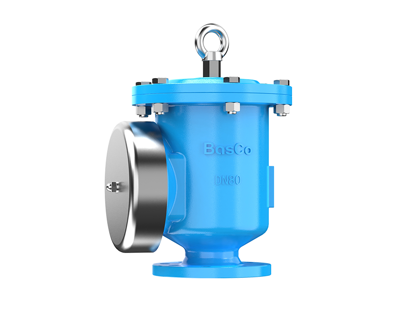
BasCo Bi-direction Explosion Isolation Flap Valve

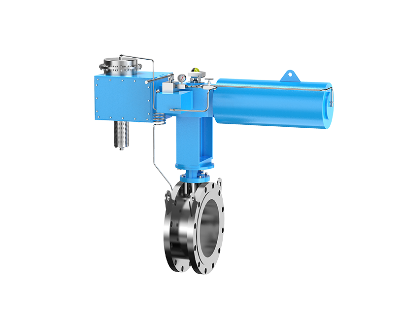
BasCo Unidirectional Explosion Isolation Flap Valve
How Does an Explosion Isolation Flap Valve Work?
Under normal operating conditions, airflow keeps the flap open and allows process air to move freely through the duct system.
When an explosion occurs, the rapidly expanding pressure wave forces the flap closed. Once closed, the valve forms a mechanical barrier that blocks flame propagation and prevents the explosion from traveling through the connected ductwork.
The entire process occurs automatically without requiring external power or electronic activation.

Comparison of unidirectional and bi-directional explosion isolation flap valve installation configurations.
BASCO explosion isolation flap valve testing demonstrates rapid mechanical closure during explosion propagation events.
What Is the Difference Between Unidirectional and Bi-Directional Flap Valves?
One of the most common questions I receive from customers concerns the difference between unidirectional and bi-directional isolation valves.
Unidirectional Flap Valves
Unidirectional valves provide protection against explosion propagation from a single direction. They are commonly installed between a dust collector and protected process equipment where airflow direction remains constant.
Bi-Directional Flap Valves
Bi-directional valves provide protection regardless of the explosion origin. They are suitable for systems where airflow may reverse or where explosion hazards exist on both sides of the valve.

Engineering comparison of airflow direction, explosion isolation capability, and application scenarios.
Where Are Explosion Isolation Flap Valves Commonly Used?
Typical applications include dust collection systems, pneumatic conveying lines, woodworking facilities, grain processing plants, chemical manufacturing facilities, biomass operations, and recycling systems.
At BASCO, dust collector protection remains one of the most common applications because collectors frequently represent the highest explosion risk within a process line.
What Are the Main Advantages of Explosion Isolation Flap Valves?
Explosion isolation flap valves provide several important advantages:
- Prevent flame and pressure wave propagation.
- Protect connected process equipment.
- Reduce secondary explosion risk.
- Operate without external power.
- Provide passive protection with minimal response delay.
From my experience, the greatest benefit is limiting explosion escalation and reducing the potential impact on adjacent equipment.
How Should Engineers Select the Right Explosion Isolation Flap Valve?
Selection should begin with understanding the actual explosion propagation path rather than simply matching pipe size.
Engineers must evaluate airflow direction, process layout, explosion source location, dust characteristics, and operational requirements.

Engineering decision flowchart for selecting unidirectional or bi-directional explosion isolation flap valves.
Key Selection Parameters
| Parameter | Engineering Impact |
|---|---|
| Duct Diameter | Determines valve size. |
| Air Velocity | Affects valve performance. |
| Dust Type | Influences certification requirements. |
| Flow Direction | Determines unidirectional or bi-directional selection. |
| Equipment Layout | Defines installation position. |
What Installation Factors Affect Isolation Performance?
Installation quality directly affects isolation effectiveness.
One of the most common engineering mistakes is installing a unidirectional valve in the wrong orientation. Incorrect airflow direction can prevent proper operation during an explosion event.
Another issue involves installation distance. Valves should be positioned according to manufacturer guidelines and applicable explosion protection standards.
At BASCO, we typically review the entire duct layout before recommending a final installation location.
How Should Explosion Isolation Flap Valves Be Maintained?
Like any safety device, explosion isolation valves require regular inspection.
Routine Inspection Checklist
- Verify flap movement remains unrestricted.
- Inspect for dust accumulation.
- Check sealing surfaces.
- Confirm actuator condition if applicable.
- Review inspection records.
Routine maintenance helps ensure reliable operation when protection is needed most.
How Should Engineers Prepare an RFQ?
At BASCO, accurate RFQs significantly improve product selection and engineering support.
The most useful information includes duct diameter, airflow rate, dust type, Kst value, operating pressure, equipment arrangement, and installation drawings.
Providing these details early allows for faster evaluation and more accurate recommendations.
FAQ
What is an explosion isolation flap valve used for?
It prevents flame and pressure wave propagation between interconnected process equipment during an explosion event.
What is the difference between unidirectional and bi-directional flap valves?
Unidirectional valves provide protection from one explosion direction, while bi-directional valves provide protection from both directions.
Can an explosion isolation valve prevent chain explosions?
Yes. One of its primary functions is preventing explosion propagation that could trigger secondary explosions.
How often should flap valves be inspected?
Inspection frequency depends on operating conditions, but regular inspection and maintenance should be part of the facility's safety management program.
Conclusion
Explosion isolation flap valves play a critical role in preventing explosion propagation through industrial duct systems.
From my experience at BASCO, selecting the correct valve type and installing it in the proper location are just as important as the valve itself. A properly designed isolation strategy can significantly reduce secondary explosion risk and improve overall facility safety.
If you are evaluating explosion isolation requirements for a dust collection, pneumatic conveying, or combustible dust processing system, BASCO can help review your application and recommend an appropriate explosion isolation solution.