

Inline vs end-of-line flame arresters is one of those topics where the definitions sound simple, but the engineering risk logic is not. The wrong device in the wrong location doesn't just“reduce protection” in a vague way—it can change the event you're designing for, shift where the explosion loads occur, and create a false sense of security that shows up later in an audit or, worse, in an incident investigation.
At a high level, both devices are trying to stop flame transmission through a flammable vapor/air mixture by quenching the flame front in a flame element. The hard part is that flame behavior depends heavily on whether the flame is unconfined (open to atmosphere) or confined (inside piping), how much run-up distance it has to accelerate, and whether the credible event is a deflagration or a detonation. Under the current explosion protection framework defined by ISO/IEC 80079, flame arresters are no longer treated as generic accessories, but as non-electrical protective devices whose suitability depends on installation location, confinement level, and the most severe credible explosion regime. In practice, inline versus end-of-line flame arresters should never be evaluated in isolation. They are one component within a broader tank protection system, where venting, pressure relief, ignition control, and explosion mitigation must function together to prevent overpressure, vacuum collapse, and flashback events.
Industry Insight
Most“cost-driven misselections” happen when a team treats an end-of-line arrester as a universal solution—because it's cheaper, simpler, and feels intuitive at the vent outlet. The problem is that many real ignition scenarios occur inside the piping system (or can be pulled into it), where the flame is confined, accelerates faster, and can transition toward detonation depending on geometry and distance.

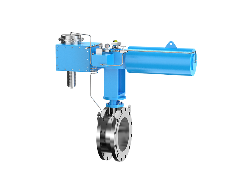
An inline flame arrester (often called an in-line arrester) is installed within the piping system—meaning the flame element sits in the pipe path between two volumes you're trying to isolate. From an ISO/IEC 80079 perspective, inline flame arresters are assessed based on the confinement and flame acceleration potential at their installation point. Because piping systems promote turbulence and flame run-up, inline devices are evaluated against more severe internal deflagration scenarios than atmospheric terminations.
Inline arresters are placed in vent lines, vapor recovery headers, interconnecting process lines, or any pipe run where a flame could travel from one part of the system to another. The key point is that you're treating the pipe itself as a credible flame propagation path, not just the tank opening.
Inline arresters are selected to address confined flame propagation. Confined deflagrations can accelerate rapidly due to turbulence, obstacles, and wall effects. With enough run-up distance relative to pipe diameter (often discussed as L/D), a deflagration can transition toward a detonation-like regime—meaning much higher flame speeds and pressure loads. Industry literature emphasizes that the run-up distance between an ignition source and the arrester heavily influences whether you should be thinking“deflagration arrester” or“detonation arrester”.
This is why inline flame arresters must be installed within the piping system when the ignition source is plausibly inside the system (or can be introduced into it). The arrester isn't there to protect the atmosphere from your vessel—it's there to prevent flame transmission through a confined pipe where flame acceleration is the real enemy.
Inline arresters are common in vapor recovery units (VRUs), vent header manifolds connecting multiple tanks, process vents routed to control devices, and any inter-tank or vessel-to-vessel connection where a flashback can turn into a line event. They're also used when a facility needs to segment risk zones—so one ignition doesn't propagate across a header and involve multiple assets.

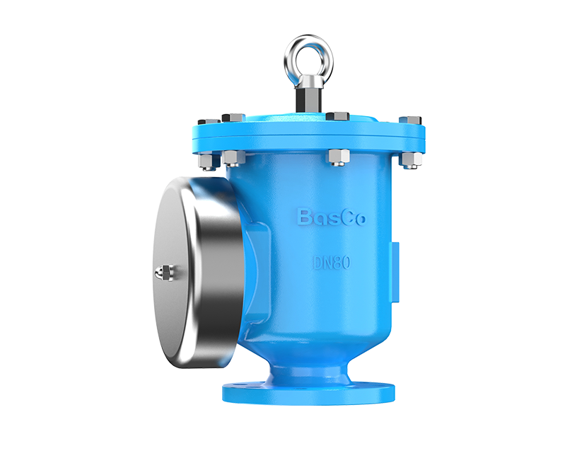
An end-of-line flame arrester is installed at a pipe termination that vents directly to atmosphere—typically on a tank vent outlet or termination point. Under ISO/IEC 80079, an end-of-line flame arrester is understood as a protective device installed at an atmospheric interface, where the credible ignition source originates outside the system and the flame is unconfined at initiation.
End-of-line units are primarily meant to stop an external ignition source—like a flashback from atmosphere, lightning-initiated flame near the outlet, nearby fire exposure, or other outside flame contact—from entering the vessel or vented equipment through the opening. In other words, the credible flame direction is“from outside to inside”, and the flame is typically unconfined at the point of ignition because it starts in open air.
End-of-line arresters primarily protect the vessel space (tank, receiver, or enclosure) from atmospheric deflagration conditions at the termination. They are not automatically sized or tested for the same pressure and flame acceleration conditions that can occur inside long pipes.
The classic misuse is installing an end-of-line arrester at the vent outlet and assuming it protects everything upstream—especially when the system includes long vent lines, a vapor recovery header, or equipment where ignition could occur inside the line. In that case, the end-of-line device may be too far from the ignition zone, and the event that reaches it may no longer resemble an“atmospheric deflagration” at all.
This is the core reason end-of-line flame arresters can be insufficient or unsafe: if the flame originates inside piping, it propagates in confinement, accelerates, and can impose much higher transient pressures on the flame element. The device might not be qualified for that regime even if it is“a flame arrester” in name.

Think in terms of risk zones, not hardware. End-of-line arresters protect the boundary between a vessel and atmosphere at a termination point. Inline arresters protect a boundary within the piping network itself, where the pipe is the hazard multiplier.
If your credible ignition source is external to the system (outside the vent outlet), end-of-line can be appropriate. If your ignition source is internal or can be introduced internally (static discharge in vapor handling, hot work ingress, flame front from connected equipment, VRU upset, or backfire paths), your risk zone is the piping system—and that's inline territory.
Both types quench flame by heat transfer through a flame element, but the event they must survive is different. Unconfined flames at atmosphere tend to have lower overpressures at the device. Confined propagation in a pipe increases turbulence and burning rate, raising pressure and pushing the system toward more severe regimes as run-up distance increases. AIChE guidance highlights the role of run-up distance (L) relative to diameter (D) in deflagration-to-detonation transition concerns.
This is also where the relationship between flame speed and installation location becomes very practical: the farther a confined flame can travel in a pipe before reaching the arrester, the more opportunity it has to accelerate. The arrester selection and location are therefore coupled decisions, not separate checkboxes.
Inline arresters nearly always have a more direct impact on process hydraulics because they sit in the flow path continuously. ISO/IEC 80079 does not explicitly prescribe inline or end-of-line flame arrester placement in simple terms. Instead, it requires that explosion protection devices be suitable for the most severe credible explosion scenario at their installation location. This risk-based approach implicitly dictates whether inline or end-of-line protection is acceptable.
In practice, inline units can introduce meaningful pressure drop, and that pressure drop can rise over time due to fouling. That matters in vent systems where backpressure affects tank design limits, blanketing control stability, or vapor recovery performance. API 2000's venting guidance emphasizes that restrictions (including devices like flame arresters) can require larger venting capacity to avoid unacceptable pressure build-up.
Maintenance is not a side issue with flame arresters—it's part of the risk model. Flame elements can foul from condensate, polymerization, particulates, corrosion products, or sticky hydrocarbons. Fouling increases pressure drop and can also reduce quenching performance if passages are compromised or heat transfer is altered.
The maintenance failure mode differs by type. End-of-line devices are exposed to weather, insects, and environmental debris at the outlet. Inline devices are exposed to process-side contamination and can become a hidden restriction that slowly changes system behavior. Either way,“it was installed correctly” is not the same thing as“it still performs as tested”, and inspection programs tend to focus heavily on element condition, differential pressure trends, and evidence of corrosion or plugging.

For a single tank vented directly to atmosphere with minimal piping, an end-of-line flame arrester is often the natural fit because the main concern is stopping external ignition from entering the tank. This aligns with how tank venting practices commonly treat termination protection, while also recognizing that any restriction can affect vent capacity and must be accounted for in sizing.
However, once you add long vent lines, common headers, or routing to a control device, the flame propagation path is no longer“at the outlet only”. At that point, an inline arrester (or even a detonation-rated arrester depending on geometry and hazard analysis) becomes a serious consideration because the piping itself is now a credible confinement path.
If a line connects process equipment where ignition could occur—through hot surfaces, catalytic effects, compressor events, or upset oxygen ingress—inline protection is typically the engineering answer. A pipe run is exactly where confined deflagration acceleration becomes credible, and it's where“distance to ignition source” stops being a theoretical concept and becomes a layout problem.
Vapor recovery systems are a common place where cost-driven misselection shows up. People see a tank vent outlet and default to end-of-line hardware, but VRU headers connect multiple tanks and equipment into a shared vapor space. That shared space creates a propagation highway. If an ignition occurs in the header or downstream equipment, the flame can travel back toward the tanks through a confined network—exactly the scenario inline arresters are meant to interrupt.

With the withdrawal of ISO 16852, flame arresters are now addressed within the broader explosion protection framework of ISO/IEC 80079, which governs non-electrical equipment used in potentially explosive atmospheres.
ISO/IEC 80079 adopts a hazard-based assessment philosophy. Rather than treating flame arresters as interchangeable components, the standard requires that protective devices be suitable for the confinement level, flame propagation characteristics, pressure conditions, and ignition scenarios present at their installation point.
This approach implicitly enforces the distinction between inline and end-of-line flame arresters. Devices intended for atmospheric, unconfined ignition scenarios cannot be assumed suitable for confined piping systems where flame acceleration and pressure rise are credible.
From an audit perspective, compliance depends not only on the presence of a flame arrester, but on whether its certification and installation align with the documented explosion risk assessment.
Auditors and internal PSM reviewers tend to focus on three practical questions. First, is the arrester type certified and applied within its tested limits (gas group/MESG, temperature, pressure, installation orientation, and distance constraints where applicable)? ISO frameworks and manufacturer documentation tie performance to these boundaries.
Second, does the physical installation match the risk narrative—meaning you can explain the credible ignition source and why the arrester location interrupts that flame path. Third, is there an inspection/maintenance program that acknowledges fouling risk, differential pressure trends, and element integrity over time.

Choosing correctly starts with one discipline: map application→credible ignition→propagation path→explosion regime→arrester type and location.
Gas group (often tied to MESG), operating pressure, temperature, and mixture composition determine whether an arrester element can quench the flame and withstand the event. ISO test frameworks and manufacturer certifications link arrester applicability to gas group and operating limits.
Pipe length matters because it drives run-up distance. A longer confined run can accelerate the flame and raise the risk that the event reaching the arrester is more severe than an atmospheric deflagration. This is why“installation location” is inseparable from“deflagration vs detonation” thinking.
In real facilities, flames don't behave like a clean textbook front. A deflagration initiated in a header can run upstream into branch lines, reflect at restrictions, accelerate through elbows and reducers, and generate pressure waves that precede the flame. If you only protect the vent outlet, you may be protecting the wrong boundary while leaving the network boundary exposed.
Inline protection becomes“mandatory” in the practical engineering sense when the credible ignition source is inside the piping system (or connected equipment) and the piping provides a confined path to equipment you must protect. That includes shared vapor headers, long vent lines, vapor recovery piping, and interconnections between vessels where flashback could spread the event. In these cases, an end-of-line device at a termination does not break the internal propagation path.
Not safely as a blanket rule. An end-of-line unit can only serve as a substitute if the protected scenario is truly an external ignition at the termination and the internal piping does not present a credible ignition or confined propagation path. If the ignition is inside the pipe network, replacing inline protection with end-of-line protection is essentially moving the“line of defense” away from the hazard—often far enough that the event can intensify before it reaches the device.
Yes, and in higher-risk networks it's common to see layered protection: an end-of-line arrester at atmospheric termination to prevent outside flashback into a tank, plus inline arresters to segment a header or protect equipment-to-equipment connections. Layering only works if you account for cumulative pressure drop and you maintain both devices so you don't accidentally create a chronic restriction that undermines venting performance. API venting logic makes it clear that restrictions affect required capacity and must be designed into the system, not bolted on afterward.
Wrong selection usually fails in one of three ways. The arrester is not rated for the explosion regime it experiences (a confined event hits a device intended for atmospheric conditions). The arrester is placed too far from the ignition zone so the flame accelerates before it reaches protection. Or the arrester becomes a maintenance-driven restriction that changes normal vent behavior and creates operational instability or overpressure exposure.
Those are not theoretical outcomes. They're exactly the kinds of causal chains that show up in incident investigations:“The system had a flame arrester” becomes irrelevant when the device didn't match the credible flame path.

|
Decision Factor |
Inline Flame Arrester |
End-of-Line Flame Arrester |
|
Primary purpose |
Stops flame transmission through confined piping between assets |
Prevents external ignition/flashback from atmosphere entering a vessel at a termination |
|
Typical installation point |
Within vent lines, headers, vapor recovery piping, interconnecting process lines |
At tank vent outlet or pipe termination venting directly to atmosphere |
|
Credible ignition location it addresses best |
Inside the system (header/equipment) or connected systems |
Outside the system at the vent outlet |
|
Explosion regime concern |
Confined deflagration; may need detonation-rated selection depending on L/D and layout |
Atmospheric/unconfined deflagration at termination conditions |
|
Pressure drop impact |
Continuous in-path restriction; DP can rise significantly with fouling |
Usually lower system-wide impact unless it becomes plugged; still affects vent capacity |
|
Common failure/maintenance risk |
Process-side fouling, hidden restriction, DP creep, performance degradation |
Weather/debris/insects at outlet, corrosion, element plugging, exposure to external fire |
|
Cost-driven misselection pattern |
Under-spec'd (deflagration-only) when layout makes detonation risk credible |
Overused as“universal solution” even when ignition is internal and piping is long/shared |
|
Best practice approach |
Place to interrupt internal propagation paths; validate gas group, pressure, temp, and run-up logic |
Use at true atmospheric terminations; don't treat as protection for long/connected piping networks |
Inline vs end-of-line flame arresters isn't a preference debate—it's a propagation-path decision. End-of-line arresters are strong tools when the hazard is external flashback at an atmospheric termination. Inline arresters become critical when the hazard is inside the piping network and the pipe geometry provides the confinement that accelerates flames and raises event severity. Standards exist because the test conditions and failure risks are different, and treating them as interchangeable is how“we had a flame arrester installed” turns into“it didn't protect what we thought it did”.
If you're evaluating a tank farm vent header, vapor recovery network, or any system with long vent lines or shared manifolds, the fastest way to reduce risk is to document the credible ignition source, map the real flame paths, and match the arrester type (and certification limits) to that scenario. If you want, tell BASCO your basic setup (service gas group/MESG if known, operating pressure range, pipe sizes, and approximate run lengths), and BASCO will translate it into an application→risk→arrester-type recommendation you can actually defend in a PHA or audit.
The main difference is the risk zone they're designed to protect. End-of-line arresters protect the vessel boundary at an atmospheric termination against external ignition. Inline arresters protect within the piping network against confined flame propagation between connected assets, where flame acceleration and higher pressures are credible.
Use inline when the piping system itself is a credible flame path—shared vapor headers, vapor recovery piping, long vent lines, and equipment interconnections—especially when ignition could occur within the network or downstream equipment and propagate back upstream in confinement.
Only in narrow cases where the credible ignition source is external at the termination and the internal network does not create a confined propagation risk. If ignition can occur inside the piping system, substituting end-of-line for inline can be unsafe because the event can intensify before it reaches the device.
ISO/IEC 80079 does not mandate specific devices by name. Instead, it requires explosion protection measures to be appropriate for the credible ignition source and flame propagation path. When confined piping creates a realistic flame acceleration risk, inline flame arresters become the technically defensible solution.
You can end up protecting the wrong boundary. A confined flame can accelerate in piping, potentially changing the regime and pressure loads that reach the arrester, which may exceed what the device was tested for. The result can be flame transmission, element damage, excessive restriction, or system overpressure—plus a compliance problem because the installation no longer matches the certification assumptions.
Often, yes—because they sit directly in the flow path continuously, and fouling can increase differential pressure over time. ISO testing frameworks treat in-line pressure drop as a defined performance parameter, and API venting logic requires you to account for restrictions in vent sizing.

How to Size a Pressure Vacuum Relief Valve According to API 2000
2026-08-18Flame Arrester Guide: Types, Applications, Selection, and Industrial Solutions
2026-08-04Common Causes of Dust Collector Explosions and How to Protect Against Them
2026-07-13BasCo conducts "CPR+AED Emergency Training to Strengthen Workplace Life Safety Defense"
2026-06-18Copyright © Jiangsu Bafang Safety Device Co., LTD. All Rights Reserved