When I walk a facility with an operations or reliability team, I usually ask one simple question early: “Where does this system breathe?” If the answer is unclear, that's a red flag—because pressure and vacuum events don't announce themselves politely. They show up as deformed tanks, pump cavitation, lifted gaskets, nuisance alarms, product loss, or worse: a safety incident.
Pressure Vacuum Relief Valves (PVRVs) are one of those components that only get attention after something goes wrong, even though they sit at the center of safe containment. Their job is straightforward: prevent overpressure and prevent vacuum collapse by opening at defined setpoints. The tricky part—and the part engineers often underestimate—is that the system determines what the valve actually “sees”. In other words, a PVRV can be perfectly sized, perfectly set, and perfectly certified, and still fail to protect what you think it's protecting if it's installed in the wrong location or in the wrong flow environment. In practice, I treat a PVRV not as a standalone valve, but as one functional element within a broader tank protection system, where venting, ignition prevention, and emergency relief must work together to prevent structural failure and hazardous releases.
That's why I like framing PVRVs less as “a valve” and more as a pressure boundary behavior tool. The placement of that tool—inline versus end-of-line—changes the physics of how pressure waves propagate, how quickly the valve experiences the true boundary condition, and how stable the valve remains under cycling. The outline and selection questions in your notes map exactly to how I approach real projects.

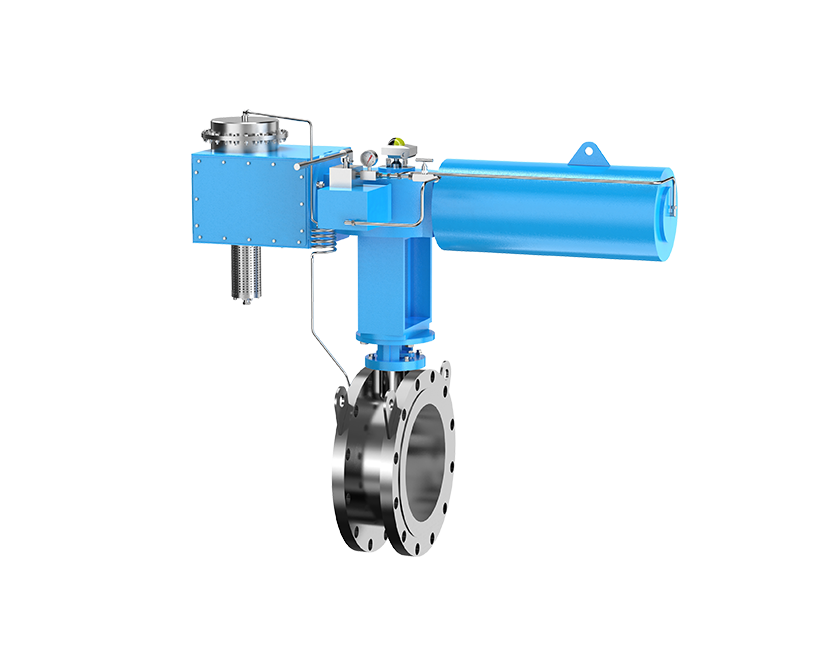
When I say “inline PVRV”, I'm describing a valve installed in the flow path of a process line or vapor line, not just at a final vent termination. Inline PVRVs show up where a pipeline, manifold, vapor recovery header, or closed-loop segment needs local protection because the pressure condition can be created internally—by pumps, thermal expansion, block-in scenarios, rapid valve closures, pigging operations, or even process upsets that generate vapor.
The key operational difference is that an inline PVRV is coupled tightly to line dynamics. If pressure rises at a point in the system near the valve, the valve can “feel” that rise quickly—sometimes much faster than an end-of-line device would—because there's less intervening volume and less pressure drop between the event location and the sensing location.
That speed is not magic. It's system physics. Inline placement can reduce the distance and resistance between the event source and the relief element. But that benefit comes with tradeoffs: you're inserting a device into the line that can become a restriction, a fouling point, or a maintenance headache if the media isn't friendly.
In my experience, inline PVRVs make the most sense when the pressure/vacuum hazard is local and dynamic, and when upstream/downstream piping cannot be assumed to transmit pressure changes cleanly to a terminal vent valve.
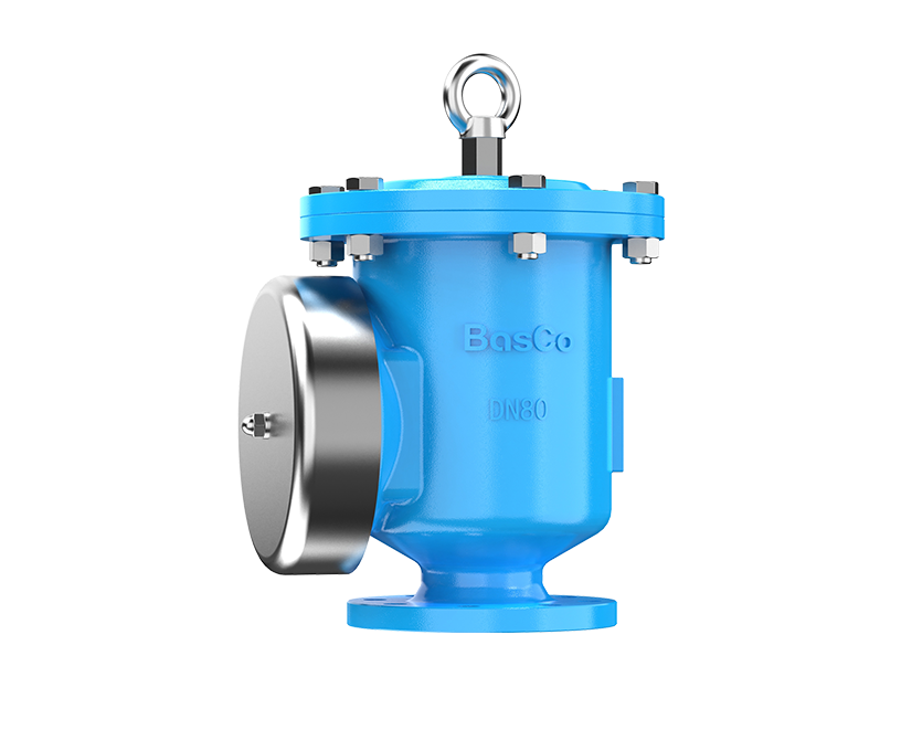
An end-of-line PVRV is what many teams picture first: a valve installed at the terminal boundary of the system—typically at the tank vent nozzle, at the end of a vent stack, or at the final connection point before atmosphere or a vapor control unit. Its primary job is to protect the vessel or controlled volume by opening when the system boundary pressure crosses a setpoint.
The phrase “end-of-line” is more than a location label. It describes protection behavior. End-of-line PVRVs typically protect the entire connected system volume as a whole—but only if the vent path between the protected volume and the valve is not creating excessive pressure drop, liquid hold-up, icing risk, or backpressure.
The practical advantage I see again and again is maintainability. End-of-line devices are often easier to access, easier to isolate safely, and easier to inspect without pulling apart process piping. That translates directly to shorter downtime windows and fewer “we'll just defer it” decisions that quietly increase risk.
The tradeoff is responsiveness to certain transient events. If a pressure spike occurs deep inside a long run of piping, the end-of-line valve may not see the same magnitude or timing of that spike due to line losses, wave reflections, and restrictions. That doesn't make end-of-line wrong—it just means you should be honest about what it can and cannot protect, based on the system between the event and the valve.
If you remember only one concept from this article, make it this: installed does not always mean protected. A valve protects what it can “see” in real time, through the impedance of the piping and the compressibility of the fluid.
Inline PVRVs become part of the line's hydraulic and pneumatic identity. They influence pressure drop, they can create turbulence, and they sit in the zone where contaminants, condensate, or particulates may naturally collect—especially if the line isn't perfectly pitched or if the operating regime includes two-phase flow.
End-of-line PVRVs, on the other hand, usually live at a boundary where the system transitions to atmosphere or a controlled vent header. That location typically reduces exposure to process debris and simplifies isolation. But it also means the valve is only as effective as the vent piping and any upstream accessories (flame arresters, condensate pots, knockouts, vacuum breakers, conservation vents, or pressure control elements).
From a system integration standpoint, inline placement tends to be chosen when you're protecting a segment that can be blocked-in or rapidly pressurized, whereas end-of-line placement tends to be chosen when you're protecting a defined volume (like a tank) with predictable breathing scenarios.

People often say “inline PVRVs respond faster”, but I don't like that statement unless we explain the “why”. The “why” is that the valve's opening is driven by the differential pressure at the valve seat, and that differential pressure is a function of how quickly the transient reaches the valve location.
In a long line, pressure transients don't teleport. They propagate as waves. Along the way, they can be damped by friction, softened by line pack, delayed by restrictions, and altered by changes in diameter, elbows, control valves, or phase behavior. If your only relief point is at the far end, the relief device may see a delayed, reduced, or distorted version of the event. In some systems, that distortion is negligible. In others—especially high-velocity vapor lines or liquid lines with fast-acting valves—it matters a lot.
Inline PVRVs can “see” the event earlier because they are closer to where pressure rises or vacuum forms. They can also reduce the required relief path length, which reduces additional pressure drop once relief begins. That can be a real advantage in systems where rapid containment is critical or where the event is localized.
But there's a caution: inline PVRVs can create new flow regimes during opening. If the valve vents into a header, the header backpressure matters. If it vents locally, dispersion and safety zoning matter. And if the system cycles frequently near setpoint, inline placement can amplify chatter risks because it experiences the raw dynamics of the line.
Line diameter and line length also matter more than most teams expect. A larger diameter line has more volume (more “cushion”), but it also can move more mass and generate different transient behavior depending on compressibility and velocity. A long run increases frictional loss and delays signal transmission. In practical terms, I treat long, narrow, restriction-heavy vent paths as a warning sign for relying solely on end-of-line protection for fast events.

Maintenance is where the “paper design” meets real operations. If a valve is hard to access, hard to isolate, or requires a shutdown of critical piping, it will get less maintenance than the risk profile demands. That's not a moral judgment—it's just what happens in plants with production pressure.
End-of-line PVRVs are often easier to reach, easier to lock out, and easier to test or swap. When you can isolate at a tank nozzle or vent connection, you can reduce the scope of the work, shorten the permit window, and reduce the number of crafts needed. That tends to reduce total cost of ownership (TCO) because labor and downtime costs dominate in many facilities.
Inline PVRVs, by contrast, can be maintenance-intensive in practice. They're in the line, so isolating them may require double block and bleed, line depressurization, draining, purging, and sometimes disassembly in tight pipe racks. That can turn what should be a straightforward inspection into a full event. Inline placement isn't “bad”, but I only recommend it when the protection value is worth the operational cost and the isolation plan is real—not theoretical.
I like to discuss failure modes in blunt system terms because it forces better decisions. The biggest mistake I see is assuming a relief valve failure is “just a valve issue”. In reality, the failure mode determines the hazard.
A stuck-closed PVRV on a tank can lead to overpressure or vacuum collapse. A stuck-open PVRV can lead to emissions, product loss, oxygen ingress, moisture ingress, or vapor recovery upset. A chattering PVRV can destroy its own seat surfaces, creating a self-worsening leak path.
Inline PVRVs add another layer: because they are in the line, a failure can become a restriction problem even when the valve isn't relieving. Fouling, corrosion products, waxy buildup, polymerizing vapors, or particulate can change the effective setpoint or reduce capacity. In viscous, corrosive, or particulate media, inline placement can be a genuine risk if the valve internals are not specifically designed and the installation doesn't avoid dead legs and liquid traps.
End-of-line valves are not immune to these issues—especially in systems with condensation, freezing, or flame arrester fouling—but they are typically easier to inspect and correct before the system drifts into a dangerous state.

When I recommend end-of-line PVRVs, it's most often for storage tanks and vessels with conventional breathing scenarios: filling, emptying, thermal breathing, and normal vapor space management. That includes fixed roof tanks, intermediate bulk storage, and many process vessels where the vent path is short and well-controlled.
Inline PVRVs show up more in pipeline and closed-loop contexts. I see them used in segments that can be blocked in, where thermal expansion can drive pressure rapidly. I also see them where vacuum conditions can occur locally—like rapid pump-out, condenser collapse, or certain inerting and purge operations.
Closed-loop systems are where the choice gets interesting. If the system is designed to remain closed and route vapors to control equipment, an inline PVRV might be used as a localized safety device, while the end-of-line device protects the primary volume boundary. In these cases, coordination matters: you don't want the “wrong” device opening first and sending flow where you didn't plan for it.
And if flame arresters and vent piping are involved, you need to treat them as part of the relief system, not accessories. A flame arrester adds pressure drop, can foul, and can change real relief performance. Long vent stacks add losses and can accumulate condensate. In my selection reviews, I always evaluate the entire path from protected volume to discharge point as one system.
I like selection logic that reads like an engineering conversation, because that's how decisions get made under schedule pressure. My “if X, then Y” approach looks like this.
If the primary hazard is tank breathing—normal filling/emptying and thermal in-and-out—then end-of-line is usually the correct starting point. It aligns with how standards and best practices generally conceptualize tank protection, and it tends to be simpler, more maintainable, and easier to audit.
If the primary hazard is a localized transient—block-in thermal expansion, fast valve closures, compressor or blower upsets, or pipeline operations—then I consider inline protection, especially if the event is likely to be attenuated before reaching an end-of-line valve.
If the vent path includes long piping runs, small diameters, multiple fittings, flame arresters, or anything that creates meaningful pressure drop, I treat “end-of-line only” as a hypothesis that must be proven with system-level analysis. Sometimes it's still fine. Sometimes it isn't.
If the media is viscous, corrosive, polymerizing, sticky, or particulate-laden, I get cautious with inline placement unless we can guarantee clean installation geometry, proper materials, and a realistic maintenance plan. In those services, an end-of-line device—located where condensation management and access are better—often wins from a lifecycle standpoint.
If the system pressure cycles frequently near the setpoint, I prioritize stability and durability. Frequent cycling can create wear, seat damage, and chatter. That can happen for both inline and end-of-line valves, but inline devices often experience sharper dynamics. In those cases, setpoint strategy, blowdown characteristics, and the influence of backpressure and header dynamics become selection-critical.
Finally, if your project is governed by API 2000 or similar standards and internal engineering practices, I align the choice with the standard's intent: protect the vessel/volume reliably under defined scenarios, and ensure the installed configuration matches the assumptions used in sizing and selection. The standard influence shows up less in “inline vs end-of-line” as a label and more in how you define the protected equipment, credible scenarios, and allowable pressure losses in the vent system.

The most common mistake I see is treating valve selection like a catalog exercise: “We need a PVRV, here's the setpoint, pick a size”. That approach ignores the fact that the system between the hazard and the valve determines whether the setpoint is meaningful.
Another mistake is assuming that adding an inline valve automatically increases safety. It can—but it can also introduce a new restriction point, a new fouling point, and a new maintenance burden. If the valve sits where liquids collect or debris accumulates, it can quietly drift into a failure mode that no one discovers until an event occurs.
I also see setpoint mismatches all the time. The system's real operating pressure, surge pressure, and vacuum potential need to be understood in operational terms, not just in design terms. A valve set too close to normal cycling will chatter; a valve set too far from the true hazard threshold may not protect in time. And if you add vent piping, flame arresters, or tie into a header, you must consider how those elements create backpressure and alter effective setpoints.
The final mistake is “false protection by installation”. Teams feel safer because a valve exists. But if the valve is located such that the protected equipment cannot transmit the hazardous condition to it in time—or if the vent path is restricted—then the system is not truly protected. That's why I keep coming back to system-level behavior as the foundation for selection.
|
Decision Factor |
Inline PVRV (Typical Reality) |
End-of-Line PVRV (Typical Reality) |
What I Do With This in Selection |
|
Best protection target |
Local line segment / transient event |
Primary vessel/volume boundary |
Define the “protected volume” first, then place accordingly |
|
Response to local transients |
Often faster (closer to event source) |
Can be delayed/attenuated by vent path |
If transients are credible, I model the path and consider inline |
|
Vent path sensitivity |
Moderate (still affected by discharge/header backpressure) |
High (vent piping and accessories dominate performance) |
I review pressure losses and accessories early |
|
Maintenance accessibility |
Often harder (in-pipe isolation, draining, purging) |
Often easier (terminal access, simpler isolation) |
TCO weighting increases for inline unless access is engineered |
|
Fouling/plugging risk |
Higher in dirty/viscous/particulate services |
Usually lower, but not immune (condensate/icing/arresters) |
Media compatibility and installation geometry become gating items |
|
Flow restriction risk |
Can become a restriction or weak point if misapplied |
Less likely to restrict process flow (not in main line) |
I avoid inline if it compromises line reliability |
|
Best fit for frequent cycling |
Possible but needs careful stability strategy |
Often more stable for tank breathing |
I prioritize stability, blowdown behavior, and realistic setpoints |
|
Overall TCO drivers |
Labor, isolation complexity, downtime risk |
Inspection frequency, emissions management, accessibility |
I quantify downtime and permit scope—not just valve price |
When I'm asked to choose between an inline and end-of-line PVRV, I don't start with the valve—I start with the system story: what is being protected, what events are credible, how the pressure or vacuum condition forms, and whether the valve will truly “see” that condition through the real vent path. Inline placement can be a powerful tool for fast, local transients, but it can also introduce restriction and maintenance risk if it's applied casually. End-of-line placement is often cleaner and easier to live with, but it can create a false sense of protection if long piping runs, accessories, or backpressure are ignored.
If you want, share your basic system description—protected equipment, vent path sketch (even a rough one), media characteristics, and whether you expect frequent cycling—and I'll translate that into a practical selection logic that matches real operating behavior, not just datasheet features.
The difference is not the internal mechanism as much as where the valve sits relative to the hazard. Inline valves are in the line and tend to protect local segments and transients, while end-of-line valves sit at the boundary and typically protect a vessel or defined system volume.
In many real systems, inline PVRVs can respond faster to local changes because they are physically closer to where the pressure or vacuum condition forms and may experience less damping through piping. End-of-line valves can still respond quickly for tank breathing, but long or restrictive vent paths can delay what the valve “sees”.
Often, yes. Inline placement usually makes isolation, depressurization, draining, and safe work more complicated, which drives downtime and labor costs. That doesn't mean you should avoid inline; it means you should choose it only when its protection advantage is worth the lifecycle burden.
They can, but I treat it as a higher-risk application. You need materials compatibility, geometry that avoids traps and dead legs, and a realistic inspection plan. If the service can foul or polymerize, the valve can become a restriction or drift in performance without obvious warning.
Absolutely. Location determines how pressure dynamics propagate to the valve, how much pressure drop exists in the relief path, how likely the valve is to see condensate or debris, and how accessible it is for maintenance.
Practically, it pushes you to define credible scenarios, size for the required relieving capacity, and account for vent system losses and configuration. It also reinforces the idea that sizing assumptions must match the installed system behavior.
Sometimes, but I don't assume so. If the protected equipment is a tank or vessel, end-of-line protection is typically the primary safeguard, and an inline valve may supplement it for local hazards. Replacing one with the other should be justified by system-level analysis, not convenience.

Common Causes of Dust Collector Explosions and How to Protect Against Them
2026-07-13BasCo conducts "CPR+AED Emergency Training to Strengthen Workplace Life Safety Defense"
2026-06-18Securing the title of "Top 100 Industry Suppliers" with proven capabilities! BasCo showcases its robust exhibits at the China Energy and Chemical Equipment Exhibition
2026-06-03Why Do External Floating Roof Tanks Still Need Breather Valves?
2026-05-26Copyright © Jiangsu Bafang Safety Device Co., LTD. All Rights Reserved